Russified matrix fonts for arduino. Pixel output using the Max72xxPanel library
Hello dear LPgenerator users!
Please note: in order to connect the font in a standard way, use the ready tool. It is easy to use and allows you to add additional fonts without extra effort:
In this post, you will learn how to add an additional font to your landing using the service Google Fonts by adding scripts.
2. Be sure to specify the alphabet, that is, the character set.
If the landing page is in Russian, then select Latin ( latin) and Cyrillic ( Cyrillic):
3. Select the font(s) you like and click " +":

4. Go to the collection of added fonts. To do this, click on the black bar below:

5. In the window that opens, the first item displays the previously selected fonts.
Remember: use a large number various fonts Google Fonts may slow down the loading of your landing page. The influence of the selected styles on page loading speed is displayed on the right.

6. If set and appearance satisfied with the added fonts, go to the "EMBED" section and completely copy the contents of the "STANDART" field:

Don't close Google tab Fonts, we still need it.
Open the desired landing page in the LPgenerator editor and click the tool "Scripts":
- in the window that opens, click "Add New Script";
- write the name of the script;
- select the position of the script "Inside the HEAD tag";
- paste the copied code;
- don't forget to save your changes.

7. Return to the Google Fonts tab.
Copy the CSS code that is generated to use the loaded fonts.

Each font uses its own CSS.
For example, for the Lobster font, the code looks like this: font-family: "Lobster", cursive;
8. Return to the LPgenerator editor and click on the element (text or button) to which you want to apply the downloaded font.
There are features of applying styles for different elements landing page.
CTA elements
To change the font style on the button, just click on it and in the advanced properties on the right add the CSS for the font (copied in the eighth step).

Landing page text blocks
In order to apply an external font to a text block for which you have already changed the font, it is not enough just to set the style in its advanced properties. You must also reset the current formatting. To do this, select the text and click the "Remove Formatting" button in the text editing block.
Attention: this will reset all changes made to the size, font style, alignment, etc.


After that, you can again specify the size, alignment, and other attributes.
If this is the first time you've created a text box on a landing page and you haven't changed its font, just click on the text and add CSS for the font in the element's advanced properties.
9. Save the changes and admire the result.
Please note: in the LPgenerator editor, the font will remain the same, additional fonts are displayed only in the preview and when visiting a published landing page.
The LED Matrix is a graphical indicator that can be used to display simple images, letters and numbers. We got acquainted in detail with the device of matrix indicators on. Then it became clear that grouping several matrices together is not an easy task. For each new row or a column of matrices, you need to add a new shift register along with wires and resistors, and in a good way also a ULN2003 chip.
Fortunately, engineers have long developed specialized microcircuits for controlling various kinds of indicators. In this tutorial, we will look at the matrix module with the MAX7219 chip. As it will become clear later, working with such a module is a pleasure.
1. LED matrix module with MAX7219 chip
The module is a board with a microcircuit, the strapping necessary for it and, in fact, a matrix indicator. Usually the indicator is not soldered into the board, but inserted into the connector. This is done so that a group of modules can first be fixed to some surface with screws, and then the matrices can be inserted into them.
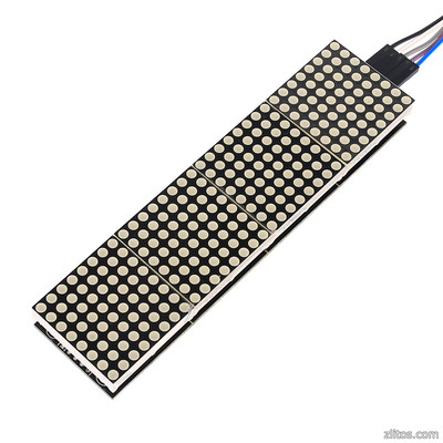
And this is how the module looks already with the matrix.

The module has five pins on each side. On the one hand, data enters the module, on the other hand, data leaves the module and is transferred to the next one. This allows you to chain matrices y.
Input connector:
- VCC, GND - power;
- DIN - data input;
- CLK - clock pulse.
Output socket:
- VCC, GND - power;
- DOUT - data output;
- CS - module selection (chip select);
- CLK - clock pulse.
The module operates on a voltage of 5 volts.
Connection
We connect the matrix module to the Arduino Uno controller as follows:
| 8×8 LED Matrix with MAX7219 | VCC | GND | CIN | CS | CLK |
| Arduino Uno | +5V | GND | 11 | 9 | 13 |
circuit diagram

Layout appearance

2. Output pixels using the Max72xxPanel library
To control the MAX7219 chip, we will use the library Max72xxPanel. You can download it from the links at the end of the lesson.
Install the library and write small program, which will display only one point with coordinates x=3 and y=4. The dot will flash with a period of 600 milliseconds.
#include
As mentioned earlier, matrix modules with the MAX7219 chip can be easily combined. It is for this purpose that at the beginning of the program we set the number of matrices horizontally and vertically. In this case, one matrix is used, so both of these parameters will be equal to 1.
It is important to note that after turning pixels on and off using the drawPixel, you need to call the function write. Without the write function, the pixels will not light up on the matrix!
Now let's write a program that will display a smiley from the past on the matrix. We will encrypt the smile using an array of eight bytes. Each byte of the array will be responsible for the row of the matrix, and each bit in the byte for a point in the row.
#include Note. The Max72xxPanel library has a setRotation function that sets the image orientation on the matrix. For example, if we want to rotate the smiley by 90 degrees, we will need to call setRotation immediately after calling the setIntensity function with the appropriate arguments: matrix.setRotation(0, 1); the first parameter is the index of the matrix, in our case it is equal to zero; the second parameter is the number of turns by 90 degrees. In a similar way, you can display any other symbol, for example, a letter, on the matrix. But in order to be able to display any letter of the English alphabet, we will need to define as many as 26 eight-byte arrays in the program! This is very dreary, and of course someone has already done this before us. In the popular Adafruit-GFX-Library, in addition to functions for working with graphics and text, there is also a base of Latin letters in upper and lower case, as well as all punctuation marks and other service characters. The link to the library is at the end of the lesson. You can display a symbol on a matrix using the function drawChar. drawChar(x, y, character, color, background, size); The first two parameters of the function are responsible for the coordinates of the upper left corner of the symbol. The third parameter is the symbol itself. The color of the symbol in our case will be equal to 1 or HIGH, since the matrix is two-color. The background is 0 or LOW. Let's make the last parameter "size" equal to 1. Let's write a program that will display in turn all the letters of the phrase: "HELLO WORLD!" #include Note. The Adafruit_GFX library has many functions for working with graphics. For example, drawCircle(3, 3, 2, HIGH) will draw a circle with center (3,3) and radius 2. The last parameter is the color, but in the case of a monochrome matrix it is 1 or HIGH. The drawLine(0, 0, 3, 6, HIGH) function will draw a line between the points (0,0) and (3,6). To display several letters at once, we need to connect several LED matrices in a chain. As mentioned earlier, this is very easy to do. The scheme for connecting six modules will look like this. circuit diagram Layout appearance Program We will make a creeping line by shifting the coordinates of the letters. To display the letter in the desired coordinates, we use the same drawChar function. #include We load the program on Arduino Uno and observe the running line! By connecting together matrix modules on the max7219, you can assemble large enough displays and use them in Arduino projects where bright images are required. LED displays, unlike liquid crystal displays, are resistant to low temperatures. For example, a running line of matrices can be placed on the street even in 30-degree frost. In addition to single-color matrix modules on the max7219, there are other similar devices. For example, three-color LED displays with a resolution of 32x16 and even 64x32 pixels. We will talk about such modules in the following lessons and articles. 1. Library Max72xxPanel: 2. Library Adafruit-GFX-Library. Writing Russian text on graphic displays with the ks0108 controller or its analogues still presents significant difficulties. The openGLCD library, which is recommended by the official Arduino sites, in the original configuration of the latter on this moment version does not contain any Cyrillic fonts, except for the font cp437font8x8. In practice, it is of little use, because in the Russian part it supports Win-1251 encoding. Therefore, to display characters in this font, they must either be inserted into the text in octal or hexadecimal codes(and there are still some ambiguities with lower case“I”, as the font creator himself points out in the comment), or still write a separate recoding function, as arduinec did for the Adafruit-GFX library. Among other things, cp437font8x8 is too big for screens of 128x64 pixels. Optimal size font for auxiliary inscriptions on such a display remains System5x7. Here we will focus on Russification precisely system font, although the reader can Russify any other font according to this sample (especially if he has a larger screen). In the process of this transformation, each character, as in any program in any programming language, is represented directly in the form of its code, that is serial number in the font table, from which the program extracts the graphic face of the corresponding character. In the font file System5x7.h openGLCD library the number of characters represented by a variable font_Char_Count type uint8_t, that is, it cannot exceed the size of one byte. Therefore, Cyrillic characters, which in UTF-8 take two bytes, cannot be transferred to the controller in the usual way. Previous attempts solutions Note that this was not always the case. Versions of Arduino 1.0.x (and, according to rumors, 1.6.0) truncated a two-byte code to a single-byte one, tritely discarding the high byte (which for Cyrillic, as follows from the UTF-8 table on the link above, is either 0xD0 or 0xD1). Therefore, to refine the font in these versions of the environment, the old GLCD v3 library is suitable, in which the font array was simply supplemented with Cyrillic characters so that their positions coincided with the low byte of the UTF-8 encoding (bytes from 0x80 to 0xBF). Such modernization is described in more detail in the author's article "Working with text on a graphic display". I repeat - it needs one of the Arduino IDE 1.0.x versions in conjunction with the GLCD v3 library, and not their more modern versions. In new versions of the Arduino IDE, it has become more and more difficult. The library strongly refuses to understand double-byte character numbers, outputting instead empty place, so a simple alteration of the font will not do here. We have to supplement it with the function of converting double-byte characters into single-byte ones. For example, for the capital Russian letter "F", the replacement string will be: Case "F": GLCD.PutChar(0xA4); break; True, a couple of liberties with ASCII table I allowed myself. The point is that in the original font System5x7.h the degree sign is placed in the last line of the table, occupying the symbol 0x80, which we already refer to the Cyrillic alphabet. In order not to violate the order of constructing the Cyrillic table in accordance with UTF-8, this line is thrown out of the file. And the degree icon is attached instead ASCII character"~" (number 0x7E), which was not used in the font for its intended purpose anyway. But such a replacement allows you to enter the degree sign in the text of the sketch directly from the keyboard in the form of the “~” symbol. Another liberties are connected with the fact that the author does not tolerate the crossed-out zero - an archaic of the times of the ADPU and monochrome text displays. Therefore, the zero in the modernized font is replaced by the glyph of the letter "O". Those who adhere to purist principles can simply delete in the font file System5x7R.h this insert (the old glyph of the slashed zero is left commented out there, its code is 0x30). In the modernized library openGLCD, which you can download from the link at the end of the article, another correction has been made - the order of connecting pins for displays with the ks0108 controller has been changed. Why this order was chosen by the author of the library (see the table at the link on the official Arduino website) is unknown. In the upgraded version, the display connection (for example, the popular MT-12864J is chosen) is carried out according to the following scheme: Wiring diagram MT-12864J An example of displaying the Russian alphabet mixed with Latin, as well as numbers and a degree icon on the MT-12864J display, is shown in the photo: The text of the sketch with the output of the Russian alphabet #include You can download the corrected version of the library Finally, matrix modules arrived from China. Each module consists of a MAX7219 chip (), an LED matrix, one capacitor and one resistor are in the harness. Controlled by MAX7219 via SPI interface. Microcircuits in a cluster are connected in series. I read on the Internet that the maximum possible serial connection allows a total of 8 pieces of MAX7219. Don't believe. 16 modules connected, and everything works fine. The modules presented on Ali come in several versions. The most popular are 2 types: with a microcircuit in DIP and in SOIC packages. DIP module bigger size and not so convenient when connecting to a cluster. You will have to connect a bunch of wires. Modules with a chip in a SOIC package are the size of an LED matrix and are connected by soldering or jumpers. It turns out nice and neat. The most well-known libraries for working with matrices and clusters are MAX72xx Panel by Mark Rice and Parola by MajicDesigns: The first library is easier to use, the second is more complex with more features. I'll write it out in more detail. Library installation required when using MAX72xx Panel Adafruit GFX.
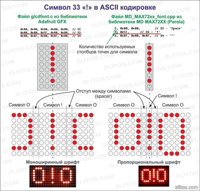
To Russify the text, you will need to download THIS FILE and replace standard file glcdfont.c in the Arduino/Libraries/Adafruit-GFX-Library-master directory. Also in this file are described, except for required letters and numbers, a bunch of all sorts of characters. Not all of them may be useful. The picture below explains how the symbols are formed. If necessary, you can create your own symbols and replace them with any unused ones in the file. Almost all bitmap fonts used in various libraries are formed in this way. So, the MAX72xx Panel and Adafruit GFX libraries are installed, the glcdfont.c file is replaced. Launch Arduino IDE, open FILE. There is a utf8rus function in the sketch. It provides recoding of the character table for the Russian language. It is needed only for normal output from the program, that is, in the program desired text written in Russian. If the text is entered via the COM port, then the character codes are corrected in the Serial_Read function. In the IDE and in the console, the developers used different encodings. At the beginning of the file there are lines necessary for the library to work. int numberOfHorizontalDisplays = 1; int numberOfVerticalDisplays = 16; I have modules with a chip in a SOIC package. They have a small feature. The matrix of the modules is installed rotated by 90 degrees. It's a convenience fee. If you run the sketches that come with the libraries, they will output text from bottom to top in each module. The text will be displayed in zigzags. To treat this ailment, the library needs to be "told" that there are 16 vertical displays (they are physically located horizontally). And then in void Setup specify the line for the library matrix.setRotation(matrix.getRotation() + 1); It will programmatically flip each matrix. And everything will be displayed normally. Modules with a DIP chip package do not have this. Everything is beautiful, except for a bunch of wires. The MAX72xx Panel library is rather modest. visual effects there is no output. The cluster is perceived as one whole. Things are much better with MD Parola. Owners of modules with a chip in a SOIC package will also face the problem of orienting modules in a cluster. Only it looks a little different than in MAX72xx. Here, the modules will appear, as it were, out of turn. HelloWorld sketch from samples included with the library. Programmatically in the sketch, I was not able to cure this ailment. I treated him differently. In the file Adruino/libraries/MD_MAX72xx_lib.h at the end you need to find the lines as in the picture. And fix the selected line selected 1 to 0. Save the file. Arduino IDE does not need to be restarted. We pour, we look. Now you can use 24 animation effects. The animation is started with the command P.displayText(“Text to display”, “text alignment”, speed, display delay, fade-in effect, fade-out effect). As you can see, there are a lot of settings.
And the most relish is the division of the cluster into virtual zones. Working with zones is not very difficult. I don’t post the sketch, it is in the samples that come with the library. Now you can display the clock at the beginning of the cluster and the news ticker on the remaining modules without any problems, almost.
As you may already guess, the problem is with Cyrillic letters. She is also resolvable. Near previous file in the same directory is the file MD_MAX72xx_font.cpp. This is a font file. The characters in it are formed similarly to the library's GFX font file. There is a slight difference. Here the character size can be less than 5 points. In the Adafruit GFX Library exclamation mark, for example, is also 5 dots wide like any other character, only one row of dots is used. The rest do not glow, but are used as a symbol. In Parola, the same exclamation mark also occupies one row of dots, only there are not empty dots nearby, but adjacent characters can be. It will be clearer to understand the picture. Append file Cyrillic characters similarly to the file from the first considered library, there is no time yet. If someone does this and sends me a file, I will add it to this article, and both I and the guests of my site will be grateful to you. Outcome. The MAX72xx Panel library by Mark Rice is easy to use and understand, but with poor functionality. The Parola library from MajicDesigns is more complex and has enough capabilities for almost any application.3. Text output using Adafruit-GFX-Library
3. Program. Running line on max7219


Tasks
Conclusion
useful links
Russification of the openGLCD library for Arduino
What's the problem?
First, let's get to the root of the problem. Wednesday Arduino IDE- it's normal text editor Windows, which works in universal UTF-8 encoding like any other in modern Windows versions(Notepad, for example). UTF-8 is an economical version of multibyte UNICODE encodings. In UTF-8, English characters, numbers, dots, commas, brackets, and any other icons are represented by a single byte, which is the same as the standard ASCII encoding. Therefore, their representation in the sketch code does not present any difficulties: after compilation, the string of English characters is transferred to the loaded hex file without changes and is understandable to the 8-bit controller, as they say, “without translation”. Decision
The author did not go into the depths of library functions, but wrote an add-on for openGLCD in the form of a function outstr(), which iterates over all elements of the input string, passing them through a select statement switch. It catches Cyrillic characters from a string and replaces them with single-byte codes corresponding to the modernized font file System5x7R.h.
Here 0xA4 is the low byte of the encoding of the letter "F" in UTF-8 (see link above). According to this encoding, new file font System5x7R.h. In principle, with this approach, any encoding of Russian characters and any other glyphs that you want to insert into the font can be used in the font. If only their total number did not exceed 128 pieces: from the beginning of the table to the character 0x7F (127 is the last character standard table ASCII) it is advisable to leave the font intact.
The variable resistor R1 is connected here according to the manufacturer's recommendations, and the resistor R2 serves to limit the current of the backlight if it is not connected to a voltage of 5 V, but directly to the input power source (Arduino Vin pin) with a higher voltage. 
Sketch text for this example:
Since the files with the function outstr.h and font System5x7R.h placed in root directory of the modernized library, then separate links should be placed on them at the beginning of the sketch using the directive #include. For English-language inscriptions, it is still convenient to use standard features println/print, but if you need to translate a line in Russian text, you must explicitly indicate the symbol "\n". 


MAX72xx Panel

Parola by MajicDesigns.