Does it make sense to repair a phone charger? How to fix a phone charger
It turned out that within a month two ordinary Chinese chargers failed. Moreover, no symptoms or hints of difficult operation of the chargers were observed. Just at one point the phone stopped charging.
And although such chargers are not that expensive, there was an interesting desire to find the reason why they stopped working after a short period of time.
Cheap Chinese chargers are non-separable, as they come in a molded case. And if you need to get to the device’s board, then the case has to be cut or sawed. The most convenient and neatest disassembly option is to saw off part of the body. Therefore, we take a hacksaw for metal and saw off the upper part, simulating the lid, in a circle.


Then remove the board from the case. We do everything carefully so as not to break off parts or damage the tracks.


Now we visually inspect the board on both sides to identify tracks and parts that have been exposed to high temperatures due to a short circuit or overloaded operation of the part.
As a rule, in places of strong heating and burnt parts, traces of soot are visible and the color of the varnish differs from the general color. Electrolytic capacitors (barrels) at the top may be swollen.


If no visible violations are found on the board, then most likely the charging circuit is “live” and in this case you need to pay attention to power supply unit, which is a weak point.
The fact is that in order to reduce the cost and automate the assembly of the charger, the manufacturer simplified the supply of voltage to its input and abandoned the wires connecting the board input to the metal rods (plugs) with which the charger is connected to the network.
The contact pads are etched onto the board, and the board itself is clamped between spring-loaded clamps and metal rods. To collect current, the board is pressed with its contact pads against the clamps and is in a clamped position between the clamps and metal rods.
As a rule, repairing such an inexpensive device is not economically profitable.
Especially in non-poor countries. Average price 5 dollars.
But it happens that there is no extra money, but there is time and spare parts.
There is no store nearby. Circumstances do not allow. Then it's not about price.
In my case, everything was simple - one of my two chargers broke Nokia AC-3E, friends brought a bag of broken chargers. Among them were a dozen branded Nokia chargers. It was a sin not to take it.
The search for the circuit did not lead to anything, so I took a similar one and converted it to the AC-3E. Many chargers for mobile phones are made using a similar scheme. As a rule, the difference is insignificant. Sometimes the denominations are changed, a little more or a little less elements, sometimes a charge indication is added. But basically the same thing.
Therefore, this description and diagram will be useful for repairing not only the AC-3E.
The repair instructions are simple and written for non-specialists.
The scheme is clickable and of good quality. 
THEORY.
The device is a blocking oscillator operating in a self-oscillating mode. It is powered by a half-wave rectifier (D1, C1) with a voltage of approximately +300 V. Resistor R1, R2 limits the starting current of the device and acts as a fuse. The blocking oscillator is based on a transistor MJE13005 and a pulse transformer. A necessary element of the blocking generator is a positive feedback circuit formed by winding 2 of the transformer, elements R5, R4 C2.
The 5v6 zener diode limits the voltage at the base of the MJE13005 transistor to within five volts.
Damper circuit D3, C4, R6 limits voltage surges on winding 1 of the transformer. At the moment the transistor is turned off, these surges can exceed the supply voltage several times, so the minimum permissible voltage of capacitor C4 and diode D3 must be no lower than 1 kV.
PRACTICE.
1. Disassembly. The screws holding the charger cover in this device have the shape of a triangular star. As a rule, there is no special screwdriver at hand, so you have to get out as best you can. I unscrewed it with a screwdriver, which, over the course of its use, had become sharpened into all sorts of crosses.


Sometimes chargers are assembled without bolts. In this case, the body halves are glued together. This indicates the low cost and quality of the device. Disassembling such a memory is a little more difficult. You need to split the body with a non-sharp screwdriver, gently pressing on the joint of the halves.
2. External inspection of the board. More than 50% of defects can be detected through external inspection. Burnt resistors and a darkened board will show you the location of the defect. A burst case or cracks on the board will indicate that the device was dropped. Chargers are used in extreme conditions, so falls from anywhere are a common cause of failure.
In five out of ten memory systems that I had the opportunity to do, they were trivial contacts bent through which 220 volts are supplied to the board.

To fix it, just slightly bend the contacts towards the board.
You can check whether the contacts are at fault or not by soldering the power cord to the board and measuring the voltage at the output - the red and black wires.


3.
Broken cord at the output of the charger. It usually breaks at the plug itself or at the base of the charger. Especially for those who like to talk while charging the phone.
Called the device. Insert the lead of a thin part into the center of the connector and measure the resistance of the wires.
4.
Transistor + resistors. If there is no visible damage, first of all you need to unsolder the transistor and ring it. It must be borne in mind that the transistor
MJE13005 the base is on the right, but it also happens the other way around. The transistor may be of a different type, in a different housing. Let's say MJE13001 looks like a Soviet KT209 with the base on the left.

Instead I installed MJE13003. You can install a transistor from any burnt-out lamp - a housekeeper. In them, as a rule, the filament of the bulb itself burns out, and the two high-voltage transistors remain intact.
5. Consequences of overvoltage. In the simplest case, they are expressed in a short-circuited diode D1 and a broken resistor R1. In more complex cases, the MJE13005 transistor burns out and inflates capacitor C1. All this simply changes to the same or similar details.
In the last two cases, in addition to replacing the burnt conductors, you will need to check the resistors around the transistor. With the diagram this will be easy to do.
A mobile phone or other device that uses a charger to charge its battery. The main reasons why a charger may fail are as follows:
Broken wire;
Failure of the charging unit;
Broken contact connection between the wire and the plug or charging unit.
Very often, the cause of failure of the charger is a break in the wire or a violation of the contact of the wire with the structural elements of the charger - the plug and the block. In this case, you can repair the charger yourself. Let's look at the principle of repairing damage to the charger wire using a specific example of repairing a Nokia mobile phone charger (with a thin plug).
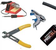
To repair the charger we will need:
Multimeter;
Soldering iron and everything needed for soldering;

If the device shows a voltage value, this indicates that the charging unit and wire are not damaged. In this case, the device showed 7 volts - this is the nominal output voltage of this charger. At this stage, we can conclude that the charger does not work due to poor contact of the conductors at the point where they are connected to the plug. You can verify this by ringing the plug with the device.
To do this, which come from the plug, insert a thin wire into the inside of the plug (this is necessary for contact with the inner contact part of the plug).
Take a multimeter and select the dialing mode. With one probe we touch one of the stripped conductors, and with the other, first to the outer contact part of the plug, and then to the inserted wire. If the device shows a contact (presence of a sound signal), this indicates that the contact between this wire and the plug is not broken.


We move the probe of the device to another stripped conductor, with the other we touch the outer part of the plug, and then the wire. If, when you touched both contact parts of the plug, the device did not emit a signal, then there is no contact. That is, one of the wires is torn off from the plug.
In this case, there are two ways: you can purchase a new plug, or you can repair the old one. The first method is simpler and more reliable. A new plug can be purchased at mobile phone repair shops or at the radio market. You may have an old charger that does not have a damaged plug.
In this case, it is enough to solder the new plug to the charger, while observing the polarity. How to check if the wires are connected correctly (polarity)? As a rule, each cord has a. If it does not match, then you need to make sure the wires are connected correctly.
To do this, plug the charger into a power socket and the new plug into your mobile phone. Connect the plug leads to the charger cord. If charging has started, then you have connected the conductors correctly. If the phone is not charging, swap the wires. The check must be performed in any case, even if the color markings of the connected cords are the same, since the markings of the cords may not match.
The next step is connecting the two cords. If you have heat shrink tubing, place part of it on one of the cords to be soldered before soldering. Solder the conductors, observing polarity. Insulate both wires with insulating tape and put on heat shrink tubing. Check the functionality of the charger.
If you do not have the opportunity to purchase a new plug, but still want to restore the charger, then the second method of eliminating the damage will suit you - repairing the plug.
Remove the rubber (plastic) covering from the plug with a knife. In this case, be careful, do not rush, as you can damage the plug itself.


The next step is to solder the charging cord to the plug.

We check the functionality of the charger. If everything is normal, insulate the conductors and put a heat-shrinkable tube on the plug. The charger is ready for use.

We examined the case of contact failure at the point where the cord is connected to the plug. There may also be another reason. Let's consider one more case.
You cut the wire, checked for voltage at the output of the charger, there is none. We cut the wire near the charger, moving 7-10 cm away from the charger block. We strip the wire that comes out of the charger block and check for the presence of voltage at the output. The presence of voltage at the output indicates that the charger is working properly. We ring the plug using the above method. In this case there is no contact failure.
Testing the charging cord showed that one of the conductors was broken. No damage is visible visually. The best option is to purchase a new wire. Then solder it to the plug and the charger block, observing the polarity.
To avoid mistakes (especially if the wires have the same color code), before soldering the wires, connect them and plug the charger plug into the phone. If charging has started, connect the conductors by soldering. Insulate the wires at the soldering site and put on a heat-shrinkable tube (it must be put on the wire before soldering). The damage has been repaired.
If the wire is intact and the contact connection of the plug is not broken, then the charging unit is damaged or one of the wires inside the unit is torn off.
Unscrew the charger unit and look at the wire connections. If all the wires are connected normally, then the memory unit itself is damaged.
If your charger unit is damaged, then, without having any skills in electrical engineering, you will not be able to find the reason for its failure, much less eliminate it yourself. Repairing the charger in a specialized service will cost you more than a new charger.
Today, many people use portable devices. The latter work autonomously and require periodic charging. For this purpose, special power supplies are used to connect the device to the mains. The charger must charge the phone, player, netbook in a certain time. If it does not cope with its functions, we are talking about a possible breakdown.
The charger can be replaced with a new one. This method is simple and accessible. But experts recommend repairing the original device. It is much more reliable than analogues and replicas on the market today. You will learn how to repair the charger yourself from the instructions below.
Device diagnostics
The basis of competent repair has always been and remains high-quality diagnostics. It is important to determine the cause of the charging failure. There may be several of these. The most common: plug malfunction, board coming out of position, wire malfunction. Most often, chargers are thrown away for the latter reason. But a broken wire is not a reason to spend money on a new device. This problem can be easily fixed with your own hands.
Charging repair: stages
If the charger wire near the power supply is broken, you must do the following:
- Disassemble the charger (unscrew the mounting bolts, remove the case).
- Cut off the broken wire and secure it with a knot in the charging case.
- Clean the ends of the wire.
- Unsolder the broken piece of wire remaining on the board (carefully so as not to overheat the sensitive element).
- Solder the stripped wire in place of the old one.
- Test the device.
If the phone is charging, the power supply can be assembled. If not, most likely the wire is broken somewhere else. In this case, the easiest way is to replace it with a new one by attaching it to the block and plug.
If the plug itself is faulty, it can be easily replaced with a new one. It is necessary to select an element of the appropriate format. The plug can be purchased at spare parts stores for mobile devices, or you can use the part from another device of a similar type and purpose.
More serious damage to the charger, as a rule, cannot be repaired. If the board burns out, theoretically it can be replaced with a new one. But there may be problems finding spare parts. In this case, it is recommended to purchase a new charger.
Now, more than ever, the number of gadgets per person has reached its maximum.
Phones, tablets, laptops, various wireless headsets - all this abundance of equipment has a power source and, accordingly, a charger for it.
The phone is not charging from the charger - what should I do?
Chargers are often carried with them in a bag or pocket, and so that they take up minimal space, their cords are twisted with a bend and tension.
This in turn leads to an almost invisible wire break and charging inoperability. Just break in the cord- this is the most common breakdown in these types of devices, and, frankly, it’s a pity to throw it away because of this.
Yes, you can, of course, buy a new one and not have to worry, but if the device is non-standard, for example, an old model phone, then it is not always possible to find such a charger. But at a flea market they might give you a block with the same problem, and no one needs the extra expenses.
Therefore, repairing a charger is a useful and worthwhile endeavor.
How to fix a charger for a phone, smartphone, tablet with your own hands
Below, this article will describe a simple repair method that does not require special equipment, which will give your charger a second life.
The photo shows a charger with a problem in the cord.
A cliff is not always visible to the naked eye. It can be hidden under the thickness of the main (top) insulation and remains almost invisible.
But, as practice shows, a fracture most often occurs near the entrance to the block or at the base of the plug.
To find the location of the break, just connect the switched-on charger to the phone and move the cord in a suspicious place.
As soon as you see that charging “started” for a moment, it means that there is a break in the place where you were moving at that moment.
In this case, upon closer inspection, the fracture and break were visible even without movement. It just happened to be at the entrance to the power supply.

The main problem in repairing such blocks is that they are not collapsible. Therefore, to get to the electronic board, you need to be careful and some effort.
Using a screwdriver and a knife, you need to pry up the base of the back cover and remove it.

You should pry where the cord enters the device. If the entrance is too tight, you can trim the rubber clamp slightly.

This must be done carefully so as not to cut the wire at all.
Using a screwdriver, we try to lift the lid up.

It may happen that it cracks in half, but more often, as in this case, the lid was removed entirely, without damage.

It was even clear that it had latches, and in the body of the charger there were recesses for them.
This means that after repair it is possible to put the cover in its place without using glue.
When the cover is removed, you need to pull the printed circuit board out of the case. Since it “sits” tightly, a screwdriver will help you get it out. By resting the blade of the screwdriver against the body and hooking its tip into one of the soldering points, we pull the board out.


The design of the case is such that when the board is inserted inside, its input contacts are connected to the clamps of the power plug pins. Therefore, when installing the board back into the case, you need to take this point into account.
The photo below shows the board with all its “internals”. The wires are soldered at the bottom.

View from the opposite side.

And here in the photo are the tracks for the input contacts.

The wire will have to be cut below the place where the damage is located. But it is very important to remember which wire is “+” and which is “-”. In some cases, the wires are color coded, with red being the positive wire and black being the negative wire.
When marking with color, you can safely cut it, and then simply solder the wires, observing the polarity.
In our case, the wires are the same color, but since the cord is flat, you can see which side of the cord the wire goes to negative and which to positive. Mark, and then cut.


Without losing the mark, strip and tin the wires on the cord.

We solder them to the board one at a time, observing the polarity.


There is usually a polarity marking on the printed circuit board at the soldering point.

To prevent the output cord from dangling, we wrap a bandage of black electrical tape around its input part. The thickness of the bandage should be such that it fits into the slot for the wire and is fixed in it.


Before installing the cover, check the operation of the device. We plug it into the network and connect it to the phone. If you don’t have your phone with you at the moment, use a DC voltmeter.
Since the internal contact in the socket has a very thin tube, and the probe of the device does not go into it, you can use a piece of thin copper wire to check.

Having inserted it into the internal contact tube, we connect the probe of the measuring device to it and the outer terminal of the plug.
The voltmeter shows that voltage is present, which means that the fault has been fixed.

Now we snap the back cover.

We connect the phone and enjoy the results of the work done.