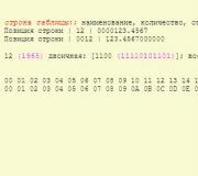
Programs for the development of printed circuit boards Russian version. Best PCB Tracing Software
Prepare PCB drawing will help free program Sprint Layout. The program is easy to use, fully translated into Russian, including a help file, and is useful in the manufacture of double-sided and multilayer printed circuit boards. Sprint Layout is rich in its capabilities; you can print contacts, conductors, shapes and text on the board. Additional features of the program include SMD mask, tin mask, metallization, control and integrated autorouter. The "Photo View" function allows you to see the printed circuit board in a realistic form.
PCB software
There are many programs for creating printed circuit boards, most of them are commercial. Sprint Layout is an excellent free alternative to its paid counterparts, supporting export to Gerber(.GBL, .GTL, .GBS, .GTS, .GBO, .GTO, .GBP, .GTP, .GKO, .GM1, .GM2, .GPT, .GPB), Excellon(Drill.DRL) and HPGL(milling) files. So if you have a computer-controlled milling or drilling machine at hand, you can process the printed circuit board more accurately using automatic systems. Its professional capabilities are not inferior to expensive programs of this kind. The archive for downloading along with the program additionally includes a folder with a set of macros that includes an extensive database of elements of domestic and foreign production. To use additional elements of the set, simply copy the contents of the "Additional Macros" folder into the "MAKROS" folder.
Official website: http://www.abacom-online.de
Operating systems:
Windows All
Supported languages: Russian
Version: 5.0
License:freeware (for free)
Automatic placement of elements and auto-routing of printed circuit boards
- DIY or Do It Yourself
Hi all!
I was prompted to write an article by a program that I came across while looking for ways to automate the development of printed circuit boards (and I didn’t find any mentions, much less articles about it on Habré). But, first things first.
So, the design has been developed, assembled on a breadboard, and tested in action. Next is the printed circuit board. If you believe the forums, many (including my friends) use Sprint-Layout. But this is manual work, the same pencil and paper, only in electronic form. Why all these processor cores and gigabytes of memory if you still have to work manually? I admit, this has always bothered me.
Now I will tell you how I achieved a satisfactory result in automatic mode.
A beautiful picture to attract attention
I used a combination of Proteus plus TopoR Lite.
I’ll say right away that I relate to these products only as a user and in no way advertise them. Moreover, Proteus can be found on the Internet (for informational purposes, of course), and TopoR Lite is free (with some restrictions).
Why these programs?
Initially I used Proteus. I don’t remember how it started, but I was quite happy with it: you can draw circuits, simulate work, and lay out boards. The first two turned out well, I didn’t like the last one, I was looking for an ideal.
I was trying to draw a diagram in Eagle. But either I’m handy, or I need special habits and dexterity, in general, I didn’t like it. At first I couldn't figure out how to add an element for a long time. Then it turned out that we needed to connect libraries with the necessary elements. How do I know what the library is called if I don’t even know the name of the element (for example, I look for connectors exclusively from pictures). Eagle by default did not have the Attiny2313 and Atmega328 I needed. I had to google/download/copy the required library. Well, the power buses in Proteus are connected right away (and even these pins are hidden on the microcircuits, so it doesn’t distract attention), but here we had to open them up clearly. The result, after half an hour of poking, was one microcircuit connected to the power supply.
I tried to draw in DipTrace. In principle, drawing is convenient. However, there is no (or I have not found) a simulation of the work; I need this both for debugging the circuit and for debugging MK programs. He became sad and returned to ISIS.
Why an external TopoR tracer if ARES has a built-in one? He's sad. Those chains that he cannot undo, he simply throws away. If this hardly happens with double-sided wiring, with single-sided and minimal board dimensions the result is terrible. And since my PCB is single-sided, and it’s more difficult to make double-sided boards, I decided that I wanted one side plus jumpers.
So, I propose to consider automation tools using a standard example from Proteus 8 - Thermo.
Scheme:

Let's go to ARES, delete all the beauty that the cunning creators of Proteus did and click on Auto-placer. This reveals another drawback of this tool: it can only place components on one side of the board (I spent half an hour looking for a solution until I read in the help that this was impossible). Those. if you use both SMD and regular cases and want them to be on different sides of the board, you will have to move the components from one side to the other with handles, each separately.

Here's what happens:

That is, he did not route 43 tracks and will have to make jumpers.
Well, let's try TopoR.
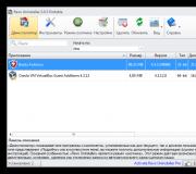
Again, click Auto-router, there Export Design File and save. Go to TopoR Import -> Specctra and open the file. Now we need to configure it a little. In the Design Parameters (F4) we delete the extra 14 layers, and in the Width of the conductors we set from 0.3 to 0.6 mm. Click the Auto-routing button, in the settings checkbox Reassign functionally equivalent contacts of components (just in case: it seemed to me that this option does not really work or even does not work at all), Single-layer routing and click the Run button. The router automatically saves the best options, which can then be added to the project. Tracing will end only after clicking the Stop button. Please note that the jumpers are placed automatically, and even contact pads are placed under them. I waited until the number of transitions reached 30 (i.e. 15 jumpers):

15 jumpers versus 43 in ARES - much better!
By spending 5 minutes and slightly moving the components/pushing the boundaries of the board, you can get 10 transitions (5 jumpers), which is already acceptable:

But as for me, moving something that’s already been thrown on for 5 minutes is much more fun than laying everything out on the board from scratch.
White circles are DRC violations (tracks/components are too close). It doesn’t matter - we manually move these same components and tracks a little and press F7 - they will be carefully re-laid, the errors are eliminated (however, I saw how this same F7 is buggy: after the next press, it puts one of the roads on top of several others, and then swears about the error) .
The TopoR-specific curvature of the tracks exudes a warm lamp-like quality and reminds us of the times when boards were drawn with a pencil on a piece of paper in a box, and drawn on the textolite with nitro paint/nitro varnish and a needle/syringe/gel pen paste. Personally, this appeals to me.
When the result is satisfactory, you can either export the board or print it directly from the program (there is even a Mirror image checkbox, apparently specifically for LUT).
Example of a real board:

You can draw polygons in TopoR, solid/line/mesh, but I forgot about them. I drew them on this board with a disk marker. The hatched spots are just jumpers.
I would be glad if the article helped someone automate tedious processes. I would be grateful if you tell me about more convenient tools for auto placement and auto routing (especially auto placement).
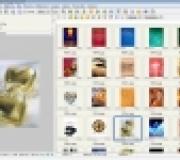
Program DipTrace is a design automation system (CAD) for creating and tracing printed circuit boards(PCB). Program DipTrace has a fairly convenient interface among programs specializing in creating circuit diagrams and tracing printed circuit boards. For greater convenience in the process of drawing, laying out circuits and boards, the program uses a highlighting mode for edited and associated radio elements.
Description of the DipTrace 2.1 program
The program has 4 modules:
- DipTrace– development of printed circuit boards, wiring, both manually and automatically;
- Schematic - drawing circuit diagrams;
- SchemEdit is an editor for the components themselves.
- ComEdit - editor of electronic components housings;
The editor of radio components and their housings uses a multi-layer design mode. It is also possible to draw and layout radio components and housings based on ready-made templates. It is possible to create cases with different parameters (number of legs, distance between them), which can later be changed directly in the PCB.
Circuit design supports the design of multi-page circuits. Using a common bus, a transition is made from one layer to another layer. The layers are connected by inter-page transitions. The created circuit diagram is transferred to a printed circuit board by selecting the appropriate menu item or pressing hot keys. The resulting board consists of component housings with electrical connections.
In manual tracing mode, DipTrace highlights all pins of network radio elements and automatically hides already wired connections. In the editing mode of already routed routes, it is possible to move part of the conductors while maintaining the angles of 90 and 45 degrees, or arbitrarily, change the width, move from one layer to another, etc. Automatic routing in DipTrace is performed using the built-in Simple Router router.
Printing of printed circuit boards and circuit diagrams on a printer is carried out at any required scale. The program exports boards to Gerber, N/C Drill, DXF formats. The Gerber program has the ability to mark technological holes. When exporting text, vectorization is performed with a given step, so you can use any font available in the program. There is also vectorization and export of raster black and white images to Gerber.
A special mode for exporting outlines to DXF makes it possible to create printed circuit boards by milling.
DipTrace has a significant number of component and package libraries. Typical libraries contain more than 40 thousand components from various manufacturers.
The material was written for the website RCOnline.ru in 2007.
Some time ago, I accidentally came across two very interesting programs on the Internet, designed for drawing basic electronic circuits and layout of printed circuit boards. Both programs were translated from German into Russian by V. Shcherbakov, which allows them to be used even by inexperienced modelers and novice electronics engineers. The programs are not interconnected and do not have such wide capabilities as the well-known packages OrCad, PCad and Accel-EDA and others, however, with their help you can draw a fairly complex circuit and trace a double-sided printed circuit board. Both programs have ready-made libraries of elements, in addition, in each of them you can easily create your own element, both circuit and PCB.
Since both of these programs were announced as Freeware, I think that I will not violate anyone’s copyright by posting them on this site.
The first program is Splan - a “drawer” of circuit diagrams. contains nine files of the “body” of the program and a bibo folder containing ready-made libraries of circuit elements. It should be noted that the set of ready-made elements, especially digital and analog microcircuits, is not very large, but the user can draw the necessary elements using the built-in editor. The program supports continuous numbering of parts of the same type.
Of course, the program allows you to draw basic geometric shapes, lines, connection points, make text inserts and inscriptions, as well as design the finished diagram in accordance with the requirements for technical drawings.
The program does not require installation as such. Simply unpack the archive file into the desired folder, and the program is ready to use. The program is designed to work under Windows of any version (Win-*, NT, 2000, XP), and takes up a little more than one megabyte on disk.
Please note that I will do all my further developments and publications with circuit diagrams and designs of printed circuit boards using these two programs!
P.S. Life does not stand still - over the past 7 years, both programs have been significantly modified by the developers. Currently relevant and. The programs have significantly greater capabilities than their predecessors, for example, Sprint-Layout can trace four-layer printed circuit boards and has much more convenient service capabilities, and sPlan is presented in a portable version that does not require installation on a hard drive. Both new versions of the programs are available in the attached archives.
Please note that output file formats created in earlier versions of programs are read by older versions, and they are usually modified to match the format of the older version. But, unfortunately, younger versions of programs do not understand files created in older versions of sPlan and Sprint-Layout.
Do you need a free PCB design tool or program to put your project into practice? So, in this list you will be presented with the 10 best programs available on the Internet and they will help you develop your PCB faster and easier. https://easyeda.com/ ru
Using EasyEDA you can order a printed circuit board. It will be possible to solder all the components together at home, or send them to the factory.
ZenitPCB
A wonderful program for creating printed circuit board layouts, aimed at implementing professional work. Using the CAD program is very easy, which allows you to bring your projects to life in a short time. With ZenitPCB it is possible to start work by entering the electrical diagram or from the wiring itself.

This program allows you to draw circuit diagrams. Includes a library of symbols to get you started developing immediately. In addition to the ability to print your sketches, you can also publish your diagrams by copying the image to a Word file or saving them in PNG format.

OsmondPCB
Universal device for developing PCBs. It runs on the Macintosh system and includes features such as: unlimited board size, multiple layers for working with the board, part numbering, support for both through-hole and surface mount, etc.

Program for constructing circuits in Windows OS. The name of the program is an abbreviation for “Basic Shematic” (author’s note). To simplify operation, only basic functions are built-in.

ExpressPCB
This program is very easy to learn and use even for beginners.

An open source program for creating electronic circuit diagrams and PCBs. Useful for everyone who works with software development.

Runs on Linux and has built-in tools for circuit design, circuit description entry, simulation, prototyping, and production. Currently, gEDA offers a sophisticated suite of free circuit design software, including description entry, attribute modification, bill of material generation, netlist with over 20 formats, analog and digital simulation, and of course PCB design capability.

PCBWebDesigner
Free CAD application for the design and production of electronic products. Create multi-layer electrical circuits with a quick and easy-to-use feature. Creating multilayer boards with copper fill support and checking the design for errors (). Built-in directory digital components with a list of materials.

DesignSparkPCB
DesignSparkPCB is the most widely used circuit design software. Easy to learn and use, designed to significantly reduce creation time from concept to finished model. These unique features are based on a powerful program engine.