Software development process. Software Design
The main stages of development are identified and characterized software. For each stage, the means that can be used to achieve the goals of the stage are presented and described.
1. Terminology
Before we begin to consider development tools that can be used to create programs, it is necessary to define the basic concepts and terms that will be used in the article. In accordance with the topic of the article basic term for us, of course, is “software development tools”. When applied to the field of software development, this definition may sound like this:
Software Development Tools– a set of techniques, methods, techniques, as well as a set of instrumental programs (compilers, application/system libraries, etc.) used by the developer to create program code A program that meets the specified requirements.
Taking into account this definition the term “Program Development” will sound like this:
Program development – difficult a process whose main purpose is to create and maintain program code that provides the required level of reliability and quality. To achieve the main goal of software development, software development tools are used.
2. Basic tools used at different stages of program development
Depending on the subject area and the tasks assigned to developers, program development can be a rather complex, step-by-step process that involves large number participants and a variety of means. In order to determine when and in what cases which tools are used, we highlight the main stages of software development. The following stages of development are of greatest interest for the issues under consideration:
- Application design.
- Implementation of application code.
- Application testing.
The steps involved in writing have been deliberately omitted here. terms of reference, planning deadlines, budget, etc. The reason for this is that at these stages, with rare exceptions, specific development tools are practically not used.
2.1 Application Design Tools
At the application design stage, depending on the complexity of the developed software product, directly depending on the requirements, the following design tasks are performed:
- Requirements analysis.
- Development of future software architecture.
- Development of devices and main software components.
- Development of user interface layouts.
The design result is usually a “Schematic Design” (Software Design Document) or “Technical Design” (Software Architecture Document). The Requirements Analysis task is usually performed using systems science (analysis and synthesis) methods, taking into account the expert experience of the designer. The result of the analysis is usually a meaningful or formalized model of the process of functioning of the program. Depending on the complexity of the process, models can be used to build these models. various methods and aids. In general, the following notations are usually used to describe models (in parentheses are software, which can be used to obtain models):
- BPMN (Vision 2003 + BPMN, AcuaLogic BPMN, Eclipse, Sybase Power Designer).
- Flowcharts (Vision 2003 and many others).
- ER diagrams (Visio 2003, ERWin, Sybase Power Designer and many others).
- UML diagrams (Sybase Power Designer, Rational Rose and many others).
- layouts, mat models, etc.
Sometimes, when a software product being developed is intended to automate any complex activity, the Analysis (Modeling) task is performed before compiling technical requirements to the future product. The results of the analysis make it possible to formulate reasonable requirements for one or another functionality of the program being developed and to calculate the real benefits from the implementation of the product being developed. Moreover, it sometimes turns out that, based on the results of the analysis, the initial goals and objectives of automation change radically, or based on the results of assessing the effectiveness of development and implementation, a decision is made not to develop the product.
The purpose of the second and third tasks from the given list of tasks is to develop a model (description) of the future system that is understandable for the encoder - the person who writes the program code. What is of great importance here is what programming paradigm (the programming paradigm must also be considered as a development tool) should be used when writing a program. As an example of the main paradigms, the following should be cited:
- Functional programming;
- Structured programming;
- Imperative programming;
- Logic programming;
- Object-oriented programming (prototyping; using classes; subjective-oriented programming).
The choice largely depends on established habits, experience, traditions, tools, which the development team has at its disposal. Sometimes the software product being developed is so complex that to solve a number of problems in different components systems use different paradigms. It should be noted that the choice of one approach or another imposes restrictions on the tools that will be used at the stage of implementing the program code. The result of solving this problem, depending on the approach, can be (software tools that can be used to obtain them are given in brackets):
- class diagram, etc. (Ration Rose, Sybase PowerDisigner and many others).
- description of structure modules and their software interface(for example, Sybase PowerDesigner and many others).
Developing user interface layouts involves creating a visual representation of how certain video forms and windows will look in the application being developed. The solution to this problem is based on the use of designer tools, which will not be discussed in this article.
2.2 Tools for implementing program code
At the stage of program code implementation, coding is performed individual components programs in accordance with the developed technical project. The means that can be used largely depend on what approaches were used during the design and, in addition, on the degree of elaboration technical project. However, among the software code development tools, it is necessary to highlight the following main types of tools (examples of tools are given in parentheses): algorithmic methods and techniques.
- programming languages (C++, C, Java, C#, php and many others);
- creation tools user interface(MFC, WPF, QT, GTK+, etc.)
- code version control tools (cvs, svn, VSS).
- tools for obtaining executable code (MS Visual Studio, gcc and many others).
- database management tools (Oracle, MS SQL, FireBird, MySQL and many others).
- debuggers (MS Visual Studio, gdb, etc.).
2.3 Program testing tools
The main objectives of testing are to check whether the functionality of the developed program meets the initial requirements, as well as to identify errors that appear explicitly or implicitly during program operation. The main testing activities include the following:
- Failure testing and recovery.
- Functional testing.
- Security testing.
- Interaction testing.
- Testing the installation process.
- Usability testing.
- Configuration testing.
- Load testing.
Among the main types of means that can be used to perform the assigned work are the following:
- code analysis and profiling tools (Code Wizard – ParaSoft, Purify – Rational Softawre. Test Coverage – Semantic, etc.);
- tools for testing functionality (TEST - Parasoft, QACenter - Compuware, Borland SilkTest, etc.);
- performance testing tools (QACenter Performance – Compuware, etc.).
3. Conclusion
The software development process is a complex process, and what tools need to be used largely depends on the tasks assigned to the developers. Regardless of the development tasks, the tools cannot be limited to just a set of some tools; it is also necessary to include methods, techniques, approaches and everything that is used to create a program that meets the specified requirements.
Also look :
Annotation: The concept of the software development process. Universal process. Current process. Specific process. Standard Process. Process improvement. Pull/Push strategies. Classic models process: waterfall model, spiral model. Phases and types of activities.
The advantage of this model is that it limits the possibility of returning to an arbitrary step back, for example, from testing to analysis, from development to working on requirements, etc. It was noted that such returns could catastrophically increase the cost of the project and its completion time. For example, if design or analysis errors are discovered during testing, correcting them often leads to a complete redesign of the system. This model allowed returns only to the previous step, for example, from testing to coding; from software, this model was actively criticized by almost every author of relevant articles and textbooks. It has become a generally accepted opinion that it does not reflect the characteristics of software development. The disadvantages of the waterfall model are:
- identification of phases and activities, which entails a loss of development flexibility, in particular, difficulties in supporting an iterative development process;
- the requirement for the complete completion of the activity phase, consolidation of the results in the form of a detailed source document (technical assignment, design specification); however, software development experience shows that it is impossible to completely complete requirements development, system design, etc. – all this is subject to change; and the reasons for this are not only that the project environment is fluid, but also that many decisions cannot be accurately determined and formulated in advance; they are clarified and specified only later;
- integration of all development results occurs at the end, as a result of which integration problems make themselves felt too late;
- users and the customer cannot familiarize themselves with the system options during development, and see the result only at the very end; thus, they cannot influence the process of creating the system, and therefore the risks of misunderstanding between developers and users/customer increase;
- the model is unstable to failures in project financing or redistribution cash, the development that has begun, in fact, has no alternatives “along the way.”
However this model continues to be used in practice - for small projects or in the development of standard systems, where iterativeness is not so in demand. With its help, it is convenient to track development and carry out step-by-step control over the project. This model is also often used in offshore projects 1 From the English offshore - outside the shore, in an expanded interpretation - outside one country. with hourly wages. The waterfall model has been incorporated as a component into other models and methodologies, such as MSF.
Spiral model was proposed by Barry Boehm in 1988 to overcome the shortcomings of the waterfall model, primarily for better management risks. According to this model, product development is carried out in a spiral, each turn of which is a specific phase of development. Unlike the waterfall model, the spiral model does not have a predetermined and mandatory set of turns; each turn can be the last in the development of the system; upon its completion, plans for the next turn are drawn up. Finally, a revolution is precisely a phase, and not a type of activity, as in the waterfall model; many things can be carried out within its framework. various types activity, that is, the model is two-dimensional.
The sequence of turns can be as follows: at the first turn a decision is made on the feasibility of creating software, at the next the decisions are made system requirements , then the system is designed, etc. The turns may have other meanings.
Each turn has the following structure (sectors):
- defining project goals, constraints and alternatives;
- evaluation of alternatives, assessment and resolution of risks; it is possible to use prototyping (including the creation of a series of prototypes), system simulation, visual modeling and specification analysis; focusing on the most risky parts of the project;
- development and testing – here it is possible to use a waterfall model or use other models and methods of software development;
- planning the next iterations - the results, plans and resources for subsequent development are analyzed, a decision is made (or not made) about a new round; analyzes whether it makes sense to continue developing the system or not; development can be suspended, for example, due to funding failures; spiral model allows you to do this correctly.
A separate spiral may correspond to the development of some software component or the introduction of regular changes to the product. Thus, the model may have a third dimension.
The spiral model is not advisable to use in projects with a low degree of risk, with a limited budget, for small projects. In addition, the lack good funds prototyping may also make the spiral model inconvenient to use.
Spiral model has not found wide application in the industry and is important, rather in historical and methodological terms: it is the first iterative model, has a beautiful metaphor - a spiral, and, like the waterfall model, was later used to create other process models and software development methodologies.
Software product development knows many worthy methodologies - in other words, established best practices. The choice depends on the specifics of the project, the budgeting system, subjective preferences and even the temperament of the manager. The article describes methodologies that we regularly encounter at Edison.
1. “Waterfall Model” (cascade model or “waterfall”)
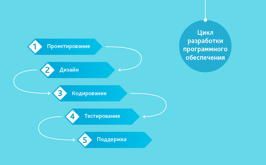
One of the oldest, involves the sequential passage of stages, each of which must be completed completely before the next begins. The Waterfall model makes it easy to manage a project. Thanks to its rigidity, development proceeds quickly, the cost and deadline are predetermined. But this is a double-edged sword. The waterfall model will give excellent results only in projects with clearly and pre-defined requirements and ways to implement them. There is no way to take a step back; testing begins only after development is complete or nearly complete. Products developed according to this model without a justified choice may have shortcomings (the list of requirements cannot be adjusted at any time), which become known only at the end due to the strict sequence of actions. The cost of making changes is high because it requires waiting until the entire project is completed to initiate it. However, the fixed cost often outweighs the disadvantages of the approach. Correcting deficiencies realized during the creation process is possible, and, in our experience, requires from one to three additional agreements to a contract with a small technical specification.
Using the waterfall model, we created many projects from scratch, including the development of technical specifications only. Projects written about on Habré: medium - , small - .
When to use the waterfall methodology?
- Only when the requirements are known, understood and recorded. There are no conflicting requirements.
- There are no problems with the availability of programmers with the required qualifications.
- In relatively small projects.
2. "V-Model"
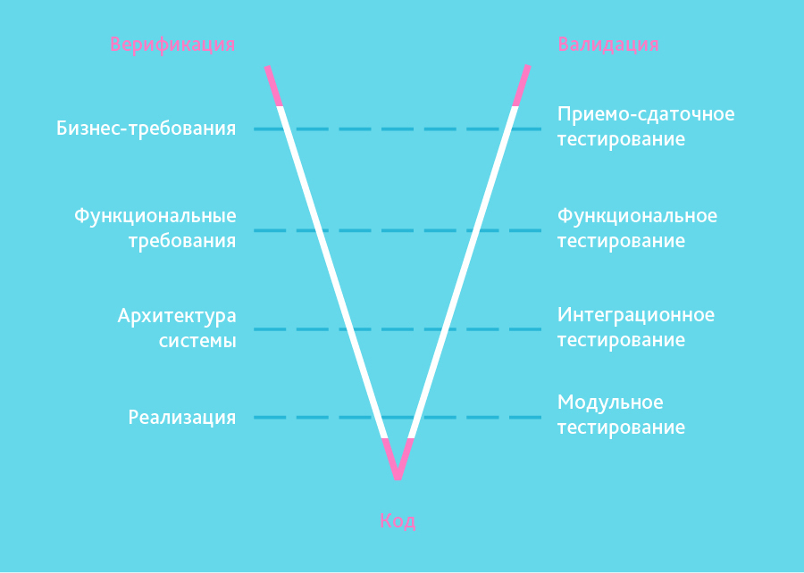
Inherited the “step by step” structure from the cascade model. The V-shaped model is applicable to systems for which uninterrupted operation is especially important. For example, application programs in clinics for monitoring patients, integrated software for control mechanisms for emergency airbags in vehicles and so on. A special feature of the model is that it is aimed at thoroughly checking and testing a product that is already in the initial stages of design. The testing stage is carried out simultaneously with the corresponding development stage, for example, unit tests are written during coding.
An example of our work based on the V-methodology - mobile application for European mobile operator, which saves roaming costs when traveling. The project is carried out according to a clear specification, but it includes a significant stage of testing: interface convenience, functional, load, and including integration, which should confirm that several components are from various manufacturers they work together stably, theft of money and loans is impossible.
When to use the V-model?
- If thorough testing of a product is required, then the V-model will justify its inherent idea: validation and verification.
- For small and medium-sized projects where the requirements are clearly defined and fixed.
- In conditions of availability of engineers with the necessary qualifications, especially testers.
3. "Incremental Model" (incremental model)
In the incremental model, the complete system requirements are divided into different assemblies. Terminology is often used to describe step-by-step assembly BY. Several development cycles take place, and together they constitute the multi-waterfall life cycle. The cycle is divided into smaller, easily created modules. Each module goes through the phases of requirements definition, design, coding, implementation and testing. The development procedure according to the incremental model involves releasing a product with basic functionality at the first large stage, and then sequentially adding new functions, so-called “increments”. The process continues until the complete system is created.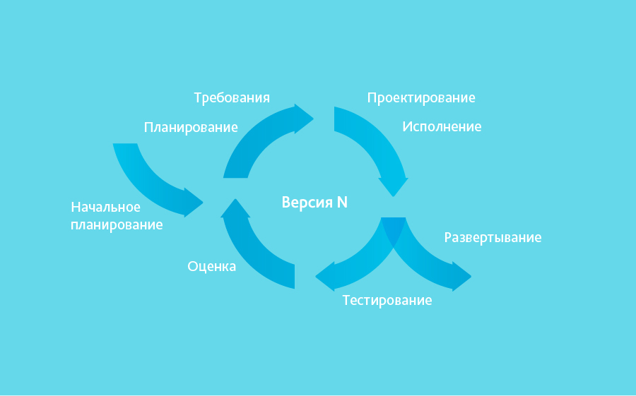
Incremental models are used where individual change requests are clear and can be easily formalized and implemented. In our projects we used it to create the DefView reader, and then the network electronic libraries Vivaldi.
As an example, we will describe the essence of one increment. replaced DefView. DefView connected to one document server and can now connect to many. A storage server is installed on the site of an institution that wants to broadcast its content to a specific audience, which directly accesses documents and converts them into required format. The root element of the architecture has appeared - the central Vivaldi server, acting as a single search engine across all storage servers installed in various institutions.
When to use the incremental model?
- When the basic requirements for the system are clearly defined and understood. At the same time, some details may be refined over time.
- Early introduction of the product to the market is required.
- There are several risky features or goals.
4. “RAD Model” (rapid application development model or rapid application development)
The RAD model is a type of incremental model. In the RAD model, components or functions are developed by several highly skilled teams in parallel, like several mini-projects. The time frame of one cycle is strictly limited. The created modules are then integrated into one working prototype. Synergy allows you to very quickly provide the client with something working for review in order to receive feedback and making changes.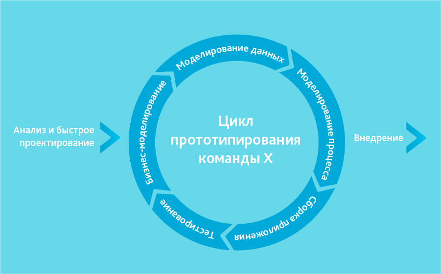
Model rapid development applications includes the following phases:
- Business modeling: defining a list of information flows between different departments.
- Data modeling: the information collected in the previous stage is used to determine the objects and other entities necessary for the circulation of information.
- Process modeling: Information flows link objects to achieve development goals.
- Build the application: Uses automated assembly tools to convert CAD models into code.
- Testing: new components and interfaces are tested.
Can only be used with highly qualified and highly specialized architects. The project budget is large to pay for these specialists along with the cost of ready-made automated assembly tools. The RAD model can be selected with confident knowledge target business and the need for urgent production of the system within 2-3 months.
5. “Agile Model” (flexible development methodology)
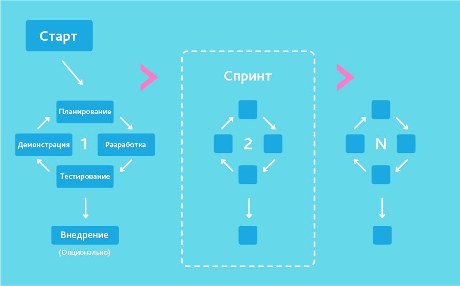
In the “agile” development methodology, after each iteration the customer can observe the result and understand whether it satisfies him or not. This is one of the benefits of the flexible model. Its disadvantages include the fact that due to the lack of specific formulations of the results, it is difficult to estimate the labor costs and costs required for development. Extreme Programming(XP) is one of the best known applications of the agile model in practice.
This type is based on short daily meetings - “Scrum” and regularly recurring meetings (once a week, once every two weeks or once a month), called “Sprint”. In daily meetings, team members discuss:
- report on the work done since the last Scrum;
- a list of tasks that the employee must complete before the next meeting;
- difficulties encountered during the work.
When to use Agile?
- When user needs are constantly changing in a dynamic business.
- Agile changes are implemented at a lower cost due to frequent increments.
- Unlike the waterfall model, the agile model requires only a little planning to get a project started.
6. “Iterative Model” (iterative or iterative model)
Iterative model life cycle does not require a complete specification of requirements to begin with. Instead, creation begins with the implementation of a piece of functionality, which becomes the basis for defining further requirements. This process is repeated. The version may not be perfect, the main thing is that it works. Understanding the final goal, we strive for it so that every step is effective, and every version is workable.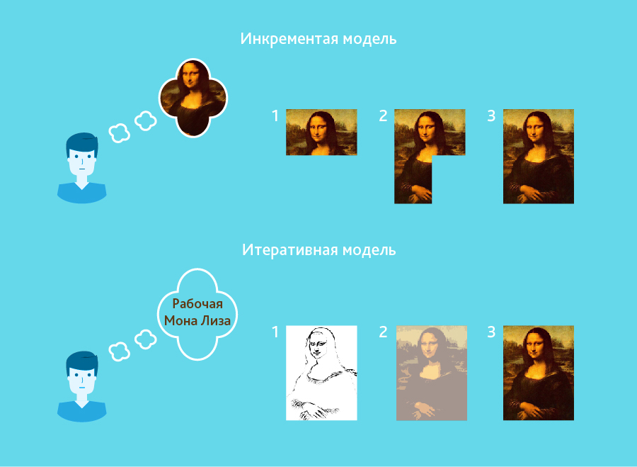
The diagram shows the iterative "development" of the Mona Lisa. As you can see, in the first iteration there is only a sketch of Mona Lisa, in the second the colors appear, and the third iteration adds details, saturation and completes the process. In the incremental model, the functionality of the product is built up piece by piece, the product is made up of parts. Unlike the iterative model, each piece represents a complete element.
An example of iterative development is voice recognition. The first research and preparation of the scientific apparatus began a long time ago, first in thoughts, then on paper. With each new iteration, the quality of recognition improved. However, perfect recognition has not yet been achieved, therefore, the problem has not yet been completely solved.
When is it optimal to use an iterative model?
- Requirements for final system clearly defined and understood in advance.
- The project is large or very large.
- The main objective must be defined, but implementation details may evolve over time.
7. "Spiral Model" (spiral model)
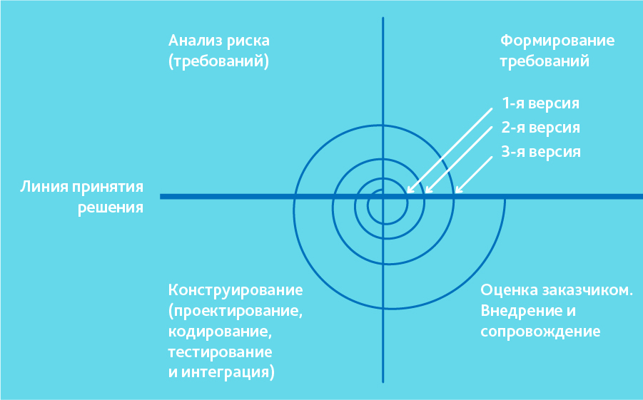
The “spiral model” is similar to the incremental model, but with an emphasis on risk analysis. It works well for solving critical business problems, when failure is incompatible with the company's activities, in the context of the release of new product lines, if necessary scientific research and practical testing.
The spiral model involves 4 stages for each turn:
- planning;
- risk analysis;
- design;
- evaluation of the result and, if the quality is satisfactory, transition to a new stage.
Let's summarize
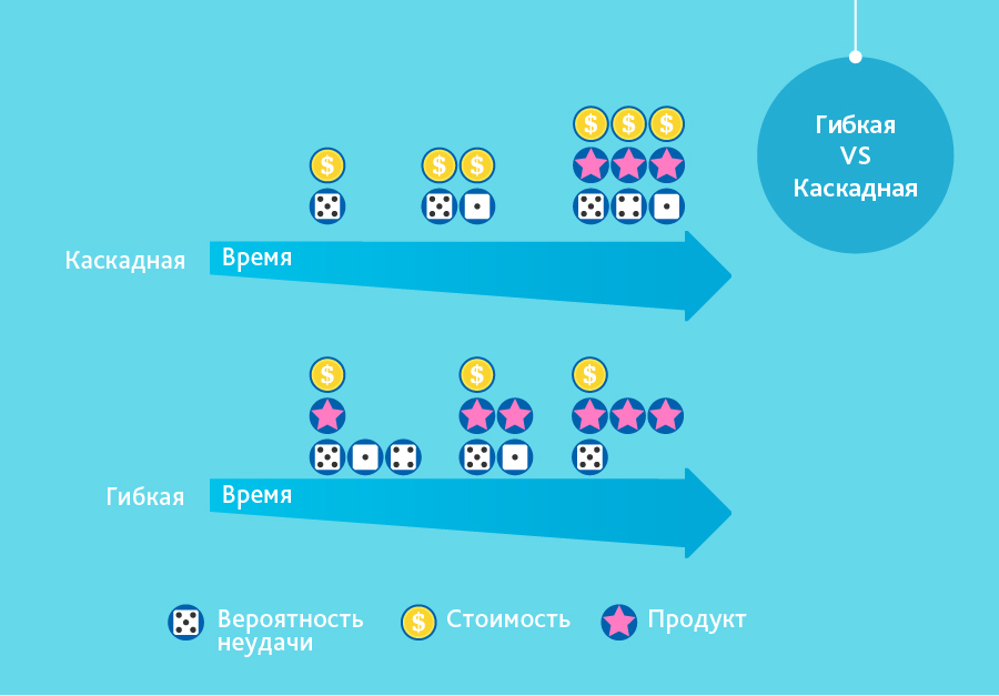
The slide demonstrates the differences between the two most common methodologies.
In modern practice, software development models are multivariate. There is no one right model for all projects, starting conditions and payment models. Even Agile, so beloved by us all, cannot be applied everywhere due to the unpreparedness of some customers or the impossibility of flexible financing. The methodologies partly overlap in means and are partly similar to each other. Some other concepts were used only to promote their own compilers and did not bring anything new into practice.
About development technologies:
.
.
.
.
What methodologies do you use?
Today the process of creating complex software applications impossible to imagine without dividing into life cycle stages. By the life cycle of a program we mean a set of stages:
- Analysis of the subject area and creation of technical specifications (interaction with the customer)
- Designing the program structure
- Coding (set of program code according to project documentation)
- Testing and Debugging
- Implementation of the program
- Program support
- Disposal
UML is graphic language for visualization, description of parameters, construction and documentation various systems(programs in particular). Diagrams are created using special CASE tools, such as Rational Rose (http://www-01.ibm.com/software/rational/) and Enterprise Architect (http://www.sparxsystems.com.au/). Based on UML technology, a unified information model. The above CASE means capable of generating code in various object-oriented languages, and also have very useful function reverse engineering. (Reverse engineering allows you to create graphic model from the existing program code and comments to it.)
Let's look at the types of diagrams for visualizing the model (this is a must have, although there are many more types):
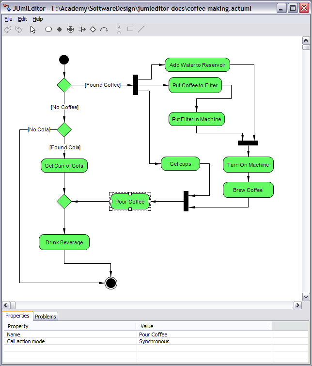
Use case diagram
The designed system is represented as a set of entities or actors interacting with the system using so-called precedents. In this case, an actor or actor is any entity that interacts with the system from the outside. In other words, each use case defines a certain set of actions performed by the system during a dialogue with the actor. However, nothing is said about how the interaction of actors with the system will be implemented.class diagram
A class diagram serves to represent the static structure of a system model in the terminology of object-oriented programming classes. A class diagram can reflect, in particular, the various relationships between individual domain entities, such as objects and subsystems, and also describes their internal structure (fields, methods...) and types of relationships (inheritance, implementation of interfaces...). This diagram does not provide information about the timing aspects of system operation. From this point of view, a class diagram is further development conceptual model of the designed system. At this stage, knowledge of the OOP approach and design patterns is essential.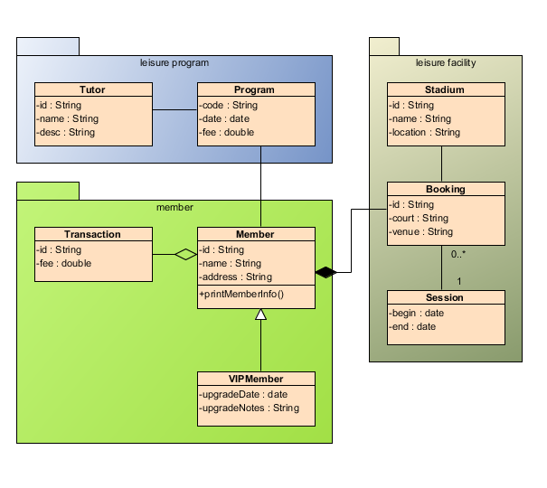
statechart diagram
The main purpose of this diagram is to describe possible sequences of states and transitions that together characterize the behavior of a model element during its life cycle. A state diagram represents the dynamic behavior of entities based on the specification of their response to the perception of some specific events.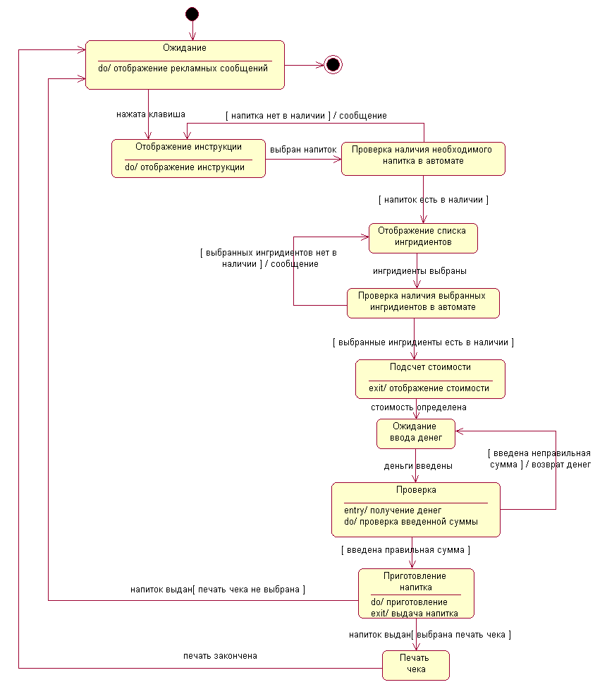
Sequence diagram
To simulate the interaction of objects in UML language appropriate interaction diagrams are used. The interactions of objects can be viewed in time, and then a sequence diagram is used to represent the timing of the transmission and reception of messages between objects. Interacting objects exchange some information with each other. In this case, the information takes the form of completed messages. In other words, although the message has informational content, it acquires the additional property of exerting a directed influence on its recipient.
Collaboration diagram
In the cooperation diagram, the objects participating in the interaction are depicted in the form of rectangles, containing the name of the object, its class and, possibly, attribute values. Like a class diagram, associations between objects are indicated in the form of various connecting lines. In this case, you can explicitly specify the names of the association and the roles that objects play in this association.Unlike a sequence diagram, a cooperation diagram depicts only the relationships between objects that play specific roles in the interaction.
Component diagram
A component diagram, unlike the previously discussed diagrams, describes the features of the physical representation of the system. A component diagram allows you to define the architecture of the system being developed by establishing dependencies between software components, which can be source, binary and executable code. In many development environments, a module or component corresponds to a file. The dotted arrows connecting modules show interdependence relationships similar to those that occur when compiling program source code. Main graphic elements Component diagrams are components, interfaces and dependencies between them.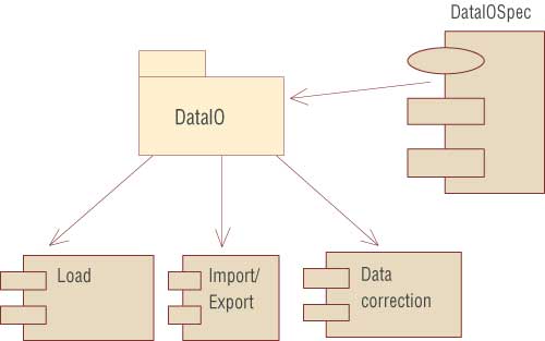
Deployment diagram
The deployment diagram is designed to visualize the elements and components of a program that exist only at the runtime stage. In this case, only program instance components that are executable files or dynamic libraries. Those components that are not used at runtime are not shown in the deployment diagram.The deployment diagram contains graphic images processors, devices, processes and connections between them. Unlike logical representation diagrams, a deployment diagram is uniform for the system as a whole, since it must fully reflect the features of its implementation. This diagram essentially completes the OOAP process for a specific software system and its development is usually the last stage of model specification.
This concludes our overview of diagrams in particular and design in general. It is worth noting that the design process has long become a standard for software development, but often you have to deal with a superbly written program, which, due to the lack of normal documentation, becomes overgrown with unnecessary side functionality, crutches, becomes cumbersome and loses its former quality. =(
I am convinced that a programmer is first and foremost a coder - he should NOT communicate with the customer, should NOT think about the architecture of the system, should not invent an interface to the program, he should only code - implement algorithms, functionality, appearance, usability, but nothing more... The designer must, starting from abstract diagrams (describing subject area) to diagrams representing the structure of data, classes and processes of their interaction, describe everything in detail step by step. That is, the complexity of the work and the salary of a designer should be an order of magnitude higher than that of a programmer == coder. Sorry for the sedition....