Types of road repair work. Manual Road Master's Handbook. Construction, operation and repair of highways. Educational and practical manual
Submitting your good work to the knowledge base is easy. Use the form below
Students, graduate students, young scientists who use the knowledge base in their studies and work will be very grateful to you.
Posted on http://www.allbest.ru/
Organization of road construction work
1. Source data analysis
1.1 Climate
The climatic characteristics of the survey area are given according to the weather station of Voronezh, Voronezh region and SNiP 23-01-99* “Construction climatology”. Road climatic zone - IV. Zone of insufficient soil moisture. It is characterized by moderate moisture in the upper layers of the soil due to significant evaporation and low precipitation.
Voronezh is located in a temperate continental climate zone. Winters are mild, with stable snow cover. There are frequent thaws. Summer is warm. There may be heat and drought. This happens when an anticyclone forms: Voronezh can easily be reached by hot air masses from Kazakhstan or North Africa. On average, about 539 mm of precipitation falls per year. The data necessary for calculations and design of the road is given in the list of climatic indicators (Table 1).
Table 1 - List of climatic indicators
|
Indicator |
Magnitude |
|||
|
1 Absolute air temperature |
minimum |
|||
|
maximum |
||||
|
2 Average outside air temperature of the coldest five-day period with a probability of exceeding |
||||
|
3 Prevailing wind direction outside |
December-February |
|||
|
June-August |
||||
|
4 Maximum of the average wind speeds by direction for January |
||||
|
5 Minimum of the average wind speeds by direction for July |
||||
|
6 Average monthly relative air humidity is the most |
cold month |
|||
|
warm month |
||||
|
7 Precipitation for |
November-March |
|||
|
April-October |
||||
|
8 Estimated snow cover thickness with a probability of 5% |
||||
|
9 Estimated depth of soil freezing |
Table 2 - Wind speed and frequency data
|
Wind speed |
|||||||||||||||||
|
Repeatability |
1.2 Relief
The city of Voronezh is located on the border of the Central Russian Upland and the Oka-Don Plain.
The relief is an undulating plain, dissected by river valleys, gullies and ravines. In the western part of the region, the predominant heights range from 172.8 to 206.3 m, in the eastern part from 151.8 to 180.9 m. The banks of the Voronezh River are relatively flat. Slopes throughout the area provide natural drainage.
1.3 Vegetation and soils
The territory of the region lies in the typical forest-steppe subzone of the forest-steppe province. Deciduous forests of oak and birch predominate. Coniferous forests and pine trees also grow. In the northwestern part of the oak forest there is a forest with an average tree height of 12 m, a trunk diameter of 17 cm and a distance between trees of 3 m. Meadow steppes with herbaceous vegetation are also common in the area. In the northern part there is a mixed forest of pine and birch with an average tree height of 15 m, a trunk diameter of 20 cm and a distance between trees of 5 m.
The main soils of the region are chernozems with a thickness of 0.4 to 0.8-1.2 m. There are sandy soils, sod-gley, meadow and swamp soil varieties.
1.4 Engineering-geological conditions
IN geomorphologically construction area in the Central Russian Upland and Oka-Don Lowland. The most ancient formations in geological terms are Devonian clays, sandstones, and limestones up to 40 m thick. They emerge on the surface along the right bank of the Voronezh River. Devonian deposits with stratigraphic unconformity are overlain by Cretaceous rocks: sands, chalk, marl.
Higher up the section are silty sands 10-12 m thick. The youngest are Quaternary deposits, represented by colluvial, sandy, glacial and eluvial sandy-clayey rocks up to 40 m thick or more.
The mineral resource base of the Voronezh region is represented by deposits of nonmetallic raw materials, mainly building materials (sands, clays, chalk, granites, cement raw materials, ocher, limestone, sandstone), especially in the western and southern regions of the region.
1.5 Information about the availability of road building materials
The territory of the region is rich in deposits of building materials (granite, sand, cement raw materials) suitable for the construction of roadbeds, laying supports and foundations of artificial and engineering structures.
This section also identifies the layers of pavement and the materials required for their construction.
1st layer - fine-grained asphalt concrete, type B, grade III (hot, dense), 5 cm thick. Used to construct the top layer of the coating. Mass fraction of crushed stone >45%.
2nd layer - coarse asphalt concrete (hot) 7 cm thick. Used for the bottom layer of the coating.
Hot mixes are prepared using liquid petroleum bitumen in a mixing plant. They are used immediately after preparation with a mixture temperature during installation of at least 120C.
3rd layer - black crushed stone using the deep impregnation method, 9 cm thick. Black crushed stone is a stone material treated with bitumen. Designed for the construction of road pavement bases. Obtained by treating crushed stone with bitumen or bitumen emulsion.
4th layer - crushed stone 16 cm thick;
5th layer - PSCHS with a thickness of 24 cm.
Roadsides are reinforced with crushed stone.
1.6 Description of the road route
The length of the route is 3000 meters. The route passes through a meadow (vegetation layer thickness 0.40 m).
1.7 Technical standards for the construction of a road section
The main elements of the designed road in plan, longitudinal and transverse profile are assigned according to SNiP 2.05.02-85 and GOST R 52399-2005. The parameters are summarized in Table 3.
Table 3 - Technical standards for the construction of a road section
|
Indicator name |
Unit of measurement |
Indicator values |
|
|
2 Design speed: main allowed in difficult areas |
|||
|
3 Motion number |
|||
|
4 Width of one lane |
|||
|
5 Width of the roadway |
|||
|
6 Curb width |
|||
|
7 Minimum width of reinforced roadside strip |
|||
|
8 Width of subgrade |
|||
|
9 Greatest longitudinal slopes |
|||
|
10 Smallest radii (basic) curves: longitudinal profile: convex concave |
1.8 Characteristic cross profilessubgrade and road pavement
Transverse profiles are assigned depending on the height of the embankment or the depth of the excavation, ground conditions along the route, taking into account the topography of the area.
In accordance with clause 6.4. SNiP 2.05.02-85 was used when designing the roadbed standard solutions. The transverse slope of the gable profile subgrade is assumed to be 40 ‰. The laying of the embankment slope up to 3 meters is 1:4, from 3 meters - 1:1.5, in the excavation - internal slopes 1:4, external 1:1.5.
2. Determining the timing of road construction work
The calendar duration of the summer construction season is determined by the climatic conditions of the area where the road section is located.
We set the start and end of work according to climatic conditions, guided by a simplified road and climatic schedule.
We carry out excavation work during the most favorable period of the year, when the soils are in an unfrozen state and their humidity is not too high. During this period it is provided required quality work performed, high productivity of machines involved in the construction of the subgrade. In this course project, construction is carried out in 2 seasons. In the first season, the roadbed is built, in the second - the road pavement.
For the subgrade:
calendar duration of the construction season 224;
number of days off (Saturday, Sunday);
number of holidays 4;
number of days of downtime due to climatic conditions
simple repair and maintenance of machinery and equipment
simple for organizational reasons and transition from one construction site to another
shift ratio
The construction of the covering layers should only begin after the installation of the lower sub-base layers, therefore the construction time is reduced against possible climatic conditions.
Table 4 - Section lengths depending on slope
Number of work shifts per season:
calendar duration of the construction season;
flow deployment period;
duration of organizational and technological break;
number of days off (Saturday, Sunday);
number of holidays;
number of downtime days due to climatic conditions;
downtime for repairs and maintenance of machinery and equipment;
shift ratio
Minimum required flow rate:
Table 5 - Calculation of the duration of road construction work
|
Name of indicators |
Name of pavement layers |
|||||
|
Add. layer of PShchS |
Lower sl. crushed stone foundations |
Upper sl. black crushed stone bases |
Bottom layer of coating made of a/b/c/z |
coating layer of a/b m/z |
||
|
The beginning and end of climate control work. conditions |
||||||
|
Estimated terms |
||||||
|
Number of working days |
||||||
3. Determining the scope of preparatory work andcalculation of the composition of the MDO for their implementation
Preparatory work is carried out before the start of work on the construction of the subgrade. These include the restoration and consolidation of the road route, right-of-way and its clearing of forest, stumps, bushes, large stones and other objects that impede the execution of work; breaking down the subgrade, cutting and moving turf cover and plant soil from the surface of the base of embankments and from the surface of excavations and reserves; planning, drainage, removal of the upper waterlogged layer; construction of temporary roads into quarries and for transportation of road construction materials, construction of ramps.
Table 6 - Removal of topsoil and vegetation layer
|
Section length, m |
Width of the area, m |
Forest felling, m 2 |
Stump removal, m 2 |
Shrub cutting, m 2 |
Area, m2 |
Volume, m 3 |
||
The driving machine is a bulldozer
Vegetation layer removal thickness
1) Productivity according to GESN 01-01-032-5 (I soil group)
Claw length for 2 bulldozers:
Layout of the natural base of the embankment in 2 passes along 1 track using a motor grader
2) Compacting the base of the embankment in 4 passes along 1 track
Table 7 - MRL for removing the vegetation layer at
4. Determination of volumes for the construction of culverts and calculation of the composition of MDO for their construction
Culverts are concentrated objects that require relatively little installation time. They are built ahead of the excavation work so that by the time the construction of the roadbed in this area begins, the construction of the pipes will be completely completed.
Table 8 - List of small artificial structures
Pipe body length without ends:
Pipe length including installation seams:
Duration of construction of culverts:
where n 1 is the time spent on installing the 1st linear meter of pipe, cm; n 2 - time spent on assembling two heads, cm; n 3 - time spent on strengthening the pipe bed and embankment slopes near the heads, see.
The culvert construction technology consists of the following operations:
1) Removal of soil and vegetation layer;
2) Layout of the axes of the pipe and the contour of the pit;
3) Construction of a pit for the pipe body and head;
4) Construction of sand-crushed stone (sand-gravel) preparation;
5) Installation of foundation blocks
6) Installation of pipe heads and body links;
7) Sealing of seams between sections and waterproofing of pipes;
8) Concreting of trays at the heads;
9) Layer-by-layer filling of the pipe body.
Composition of the team for the construction of reinforced concrete pipes:
Automotive crane KS-3573 1 pc.;
Bulldozer DZ-110A 1 pc.;
Roller with pneumatic tires weighing 25 tons or more 1 pc.;
Power station PES-12M 1 pc.;
Electric vibrators:
IV-101 1 piece;
IV-47B 1 piece;
IV-113 1 piece;
Bitumen boiler capacity. 400 l 1 piece;
Labor force per shift:
Machinists and mechanics 7 people;
Road workers 10 people.
5. Drawing up a schedule for the distribution of earth masses
The foundation soil of the future highway is suitable for the construction of a subgrade. Subsequently, the soil from the excavations will be distributed to fill the subgrade into nearby embankments.
Sections of the embankment from PC 0+00 to PC 5+00 are erected by bulldozer from lateral reserve soil. All other sections of embankments are constructed from excavation soil. There is no need to transport soil from quarries. This scheme construction of the roadbed comes down to minimizing the cost of excavation work.
All excavations are developed by an excavator with a bucket capacity of 2.5 m 3.
6. Calculation of the composition of the MDO for the construction of the roadbed
6.1 MDO for the construction of an embankment up to 1mfrom the soil lateral reserveand with a bulldozer PK 0+00 - PK 5+00
1) Development and movement of soil from the lateral reserve to the embankment at a distance of up to 10 m to fill the lower layer with a height of 0.76 m (average height) of gravel soil
The driving machine is a bulldozer
According to GESN 01-01-032-5 (soil group I):
2) Layer-by-layer compaction of an embankment with a roller in 10 passes along 1 track
According to GESN 01-02-001-1
3)
According to GESN 01-01-036-4
4)
According to GESN 01-02-027-12
5) Compacting the top of an embankment with self-propelled rollers in 2 passes along 1 track
According to GESN 01-02-001-1
6)
According to GESN 01-02-042
Table 9 - Construction of an embankment up to 1 m high from the side reserve soil with a bulldozer at
|
Rationale |
for capture |
Performance |
|||||
|
Development and movement of soil (I) into the embankment and leveling with a bulldozer for the lower layer |
GESN 01-01-032-5 |
||||||
|
Layer-by-layer compaction of the bottom layer with a roller on pneumatic tires weighing 25 tons in 10 passes along 1 track |
GESN 01-02-001-1 |
||||||
|
Development and movement of soil (I) into the embankment and leveling with a bulldozer for layer I |
GESN 01-01-032-5 |
||||||
|
Layer-by-layer compaction of the first layer with a roller on pneumatic tires weighing 25 tons in 10 passes along 1 track |
GESN 01-02-001-1 |
||||||
|
Development and movement of soil (I) into the embankment and leveling with a bulldozer for layer II |
GESN 01-01-032-5 |
||||||
|
Layer-by-layer compaction of the second layer with a roller on pneumatic tires weighing 25 tons in 10 passes along 1 track |
GESN 01-02-001-1 |
||||||
|
Development and movement of soil (I) into the embankment and leveling with a bulldozer for layer III |
GESN 01-01-032-5 |
||||||
|
Layer-by-layer compaction of the third layer with a roller on pneumatic tires weighing 25 tons in 10 passes along 1 track |
GESN 01-02-001-1 |
||||||
|
Layout of the top of the roadbed and the bottom of the reserves, giving the bottom of the reserve a slope towards the road axis using a bulldozer |
GESN 01-01-036-4 |
||||||
|
Leveling embankment slopes and side reserves using a motor grader in two directions |
GESN 01-02-027-12 |
||||||
|
Compacting the top of an embankment with a self-propelled roller in 2 passes along 1 track |
GESN 01-02-001-1 |
||||||
|
Strengthening embankment slopes and the bottom of reserves using hydroseeding |
GESN 01-02-042 |
6.2 MDO on yconstruction of an excavation with excavation of soil using an excavator. IIcategory,
1) Development and movement of soil with an excavator with a bucket capacity of 2.5 m 3
According to GESN 01-01-012-1
2) Transportation of soil with = 1.8 t/m 3 (coarse sand) over a distance of up to 1.5 km by dump trucks with a lifting capacity of 14 t
3) Cleaning excavation slopes with a grader in 1 pass
According to GESN 01-01-108-1
4)
According to GESN 01-02-027-8
5)
According to GESN 01-02-027-1
6)
According to GESN 01-01-047-1
7)
According to GESN 01-02-001-1
8) Strengthening embankment slopes and the bottom of reserves using hydroseeding
According to GESN 01-02-042
Table 10 - Composition of the MDO for the development of an excavation 3.84 m deep with an excavator at
|
Name of technical operations |
Rationale |
for capture |
Performance |
||||
|
Development and movement of soil using an excavator with a bucket capacity of 2.5 m 3 |
GESN 01-01-012-1 |
||||||
|
Transportation of soil with = 1.8 t/m 3 (coarse sand) over a distance of up to 1 km by dump trucks with a lifting capacity of 14 t |
|||||||
|
Cleaning excavation slopes with a grader in 1 pass |
GESN 01-01-108-1 |
||||||
|
Leveling slopes with a motor grader in 2 passes |
GESN 01-02-027-8 |
||||||
|
Leveling the top of the subgrade in 2 passes with a motor grader |
GESN 01-02-027-1 |
||||||
|
Cutting ditches with a motor grader during a working stroke in one direction |
GESN 01-01-047-1 |
||||||
|
Compacting the top of the subgrade with a self-propelled roller on pneumatic tires in 2 passes |
GESN 01-02-001-1 |
||||||
|
Strengthening embankment slopes and the bottom of reserves using hydroseeding |
GESN 01-02-042 |
6.3 MDOon inembankment constructionh r=2,26 mexcavation from the groundexcavator and transporterhow many dump trucksatL zah= 35 m
The construction of the embankment is carried out layer by layer.
The first layer of backfilling of the removed PRS - 0.4 m
1-8 layer - 0.25 m
9th layer - 0.26 m
The leading machine is an excavator developing the excavation. with a grip length of 10 m.
According to GESN 01-01-016
2)
3)
According to GESN 01-02-027-2
4)
According to GESN 01-02-027-12
5) Strengthening embankment slopes and the bottom of reserves using hydroseeding
According to GESN 01-02-042
Table 11 - Composition of the MDO for the construction of an embankment using an excavator from concentrated reserve soil at
|
Name of technical operations |
Rationale |
for capture |
Performance |
||||
|
Layer-by-layer leveling of soil with a bulldozer |
GESN 01-01-016 |
||||||
|
Layer-by-layer compaction of an embankment layer with a 25 t roller in 10 passes along 1 track |
|||||||
|
Layer-by-layer leveling of soil with a bulldozer |
GESN 01-01-016 |
||||||
|
Layer-by-layer compaction of an embankment layer with a 25 t roller in 10 passes along 1 track |
|||||||
|
Layer-by-layer leveling of soil with a bulldozer |
GESN 01-01-016 |
||||||
|
Layer-by-layer compaction of an embankment layer with a 25 t roller in 10 passes along 1 track |
|||||||
|
Leveling the top of the subgrade using a motor grader in 2 passes |
GESN 01-02-027-2 |
||||||
|
Leveling embankment slopes using a motor grader |
GESN 01-02-027-12 |
||||||
|
Strengthening embankment slopes and the bottom of reserves using hydroseeding |
GESN 01-02-042 |
References
road subgrade construction
1 Egorushkin, V.O. Roadbed construction technology highways: guidelines for coursework and diploma design for students of specialty 291000 “Highways and Airfields.” / - KrasGASA, Krasnoyarsk, 2003. - 51 p.
2 Design of highway subgrade: Guidelines for a course project for students of specialty 291000 “Highways and Airfields”; /KrasGASA, Krasnoyarsk, 2002. - 54 p.
3 Popov, V.G. Construction of highways (a manual for foremen and work producers of road organizations)
4 SNiP 3.06.03-85 Highways Gosstroy USSR - M.: 1989 - 56 p.
5 SNiP 2.05.02-85 Highways Gosstroy USSR - M.: CITP, 1986.
6 Yankovsky, O.A. Culverts under embankments - M.: Transport, 1982 - 232 p.
7 Gibshman, M.E., Dedukh, I.E. Bridges and structures on highways: a textbook for highways. technical schools. - M.: Transport, 1981. - 399 p.
9 Construction of highways: reference book. road engineer / V.A. Bochin, M.I. Weizman, E.M. Zeiger, E.F. Levitsky, B.S. Maryshev, Yu.M. Sementovsky, I.A. Stolyarskaya, A.A. Stromberg, V.M. Yumashev; M.: Transport, 1980.
Posted on Allbest.ru
Similar documents
Drawing up a project for major repairs when changing the plan and longitudinal profile of the road and when performing work on constructing the roadbed. Repair of asphalt concrete pavements, road pavements, drainage and artificial structures on the highway.
test, added 01/17/2012
Natural stone and other road building materials. Finishing and arrangement of roads. Technical control during the construction of logging roads. Ecological and aesthetic aspects of design and construction. Methodology for calculating flexible road pavements.
test, added 02/19/2010
Characteristics of the area of construction and operation of the highway. Calculation of the need for machines and mechanisms for preparatory work. Installation of reinforced concrete pipes and construction of subgrade. Drawing up a production schedule.
course work, added 01/12/2011
Roadbed construction technology. Determination of flow parameters, operational performance. Calculation of specific technological indicators of SCM operation: cost of production, labor, metal and energy intensity per unit of production.
course work, added 06/18/2011
Research into the technology of constructing the roadbed using the in-line method, determining the volume and timing of construction work, selecting machines and mechanisms for carrying out the work. Characteristics of quality control of work, decisions on labor and environmental protection.
course work, added 06/08/2011
Selection of methods for organizing road construction work. General information about the flow method of organizing road construction work. Construction of schedules for organizing road construction works using the in-line method. Basic parameters of road construction flows.
abstract, added 04/13/2008
Study of preparatory work during the construction of highways. Determining the scope of work to clear the road. Calculation of the need for machines, mechanisms, labor. Construction of the subgrade. Way of life upper layers road clothing.
practice report, added 09/21/2015
Constructing a diagram of traffic intensity and establishing the category of the road. Road design in plan. Calculation of the volume of work on filling the subgrade and installing pipes. Determination of the estimated cost of road construction and road transport costs.
course work, added 03/09/2016
Construction of a section of road subgrade. Determination of the geometric capacity of an excavator bucket. Process construction of the roadbed with bulldozers. Soil compaction technology. Finishing the subgrade, strengthening slopes.
course work, added 04/27/2016
Physiographic characteristics of the construction area. Construction of the subgrade in the excavation and embankment. Construction of structures to regulate the water-thermal regime of the subgrade. Planning, finishing and strengthening work in the embankment.
All work related to the construction of highways can be divided into three groups:
Construction and installation- aimed at creating final products. When constructing a subgrade, these include:
1. Preparatory work:
Restoration and consolidation of the route;
Clearing the road from forest, bushes, stumps, stones, etc.;
Laying out the subgrade;
Removing the plant layer;
Providing drainage.
2. Main works:
Loosening the soil;
Development, movement and laying of soil;
Layer-by-layer leveling;
Seal.
3. Finishing work:
Layout of the subgrade;
Strengthening the slopes of the subgrade;
Land reclamation.
Construction and installation work during the construction of the subgrade is divided into linear and concentrated. Linear work is called work whose volumes are evenly distributed throughout the road under construction and are repeated at every kilometer with only a slight deviation. Concentrated work is work that differs sharply in volume and technology from work performed in adjacent areas.
Procurement refers to work on the procurement of road building materials, the preparation of mixtures, the production of slabs, blocks and other products. These works are performed at manufacturing plants; they have some advantages in comparison with construction and installation work, namely:
Constancy of place of work and technology;
Best conditions labor;
Less dependence on weather and climatic conditions.
Transport called work on moving soil, road construction materials.
Warehouse work are inextricably linked with all types of work. They include reception, unloading, sorting, storage within the warehouse area. Warehouse work guarantees the rhythmic work of a construction organization, but at the same time increases overhead costs.
Construction and installation, procurement, transport and warehouse work must be closely interconnected.
The technological process for constructing road pavement includes:
Preliminary procurement of stone materials;
Transportation and storage of materials in warehouses;
Preparation of various mixtures, products and their transportation;
Distribution of stone materials, semi-finished products and their compaction.
Highway builders, in addition to subgrade and road pavement, construct culverts, bridges, road maintenance service buildings, and develop highways.
The percentage ratio between individual types of work is approximately as follows:
Preparatory work 1...3
Subgrade 15...40
Bridges and other artificial structures 8...12
Road clothing 40...60
Path conditions 3...5
Road maintenance service buildings 1...2
1. Selection of methods for organizing road construction work
2. General information about the flow method of organizing road construction work
3. Construction of schedules for organizing road construction works
in-line method
4. Main parameters of road construction flows
5. Literature
1. SELECTION OF METHODS FOR ORGANIZING ROAD CONSTRUCTION
The method of organizing work determines the fundamental direction of solving the main organizational issues: the sequence of work and their mutual coordination, the structure of specialized units, the arrangement, the order of movement and interaction of labor and material and technical resources, the supply system of materials, the procedure for putting the road into operation, etc.
Used in highway construction various methods organization of work. In Russia, the flow method is recognized as the most progressive and scientifically sound. In some cases, non-flow methods are used. Sometimes road construction is organized in such a way that part of the work (usually most) is carried out using the in-line method, and part - non-in-line.
The choice of method in each particular case depends on many reasons, of which the first place should be given to: the general level of development of road technology and science; the presence of appropriate material and technical base and production capacity of the construction organization conducting the construction; geographical features of the construction area; special conditions, inherent only to this object.
In the vast majority of highway construction, work should be organized using the in-line method. Its advantages are especially effective in the construction of large highways, as well as in the construction of other types of long-distance roads.
The use of non-flow methods for organizing work may be justified on certain short sections of roads (approximately 3-5 km or less), during construction in difficult conditions, within settlements, in very rough terrain, etc. However, in these cases, you should always check the possibility of organizing continuous construction. In each specific case, the final decision is made after careful evaluation and comparison various options organization of work, using a number of technical and economic indicators.
2. GENERAL INFORMATION ABOUT THE FLOW METHOD OF THE ORGANIZATION
ROAD CONSTRUCTION WORK
The flow method of organizing production is called one that ensures continuous and uniform production, as well as continuous and uniform use of labor, material and technical resources.
This characteristic of two sides of the production process (product output and resource use) is valid for any continuous production, including road construction. However, the conditions in which the production process takes place do not always provide the possibility of comprehensive compliance with all the requirements of continuous production.
The most favorable conditions for the flow are the conditions of machine factory production, which takes place in closed workshops, has stable technology and more or less constant quality indicators of the starting materials.
The linear nature of road objects contributes to the successful use of the flow method of organizing road construction work.
The essence of the flow method in the specific conditions of road construction is as follows:
in equal short periods of time (shift, day), the construction of equal length sections of the road is completed, and the finished road is built up as a continuous strip in one direction;
all work is performed by mechanized teams (units), specialized in the main types of work and equipped with appropriately selected sets of road-building machines;
specialized teams move evenly one after another along the road under construction and consistently carry out all construction and installation work;
After the last detachment has passed, the road is completely ready for commissioning.
The main types of work during the construction of highways using the in-line method are performed in the following technological sequence:
preparatory work, first of all, the construction of temporary residential buildings and the organization of communications, as well as the construction of buildings and structures of industrial enterprises, installation of their equipment and preparation for the deployment of a complex flow on the road;
construction of buildings and structures of road linear and motor transport services;
construction of medium and big bridges and other engineering structures on the road;
construction of small artificial structures;
carrying out concentrated work on the construction of the subgrade;
construction of the roadbed and strengthening works;
construction of road pavement (base and coating);
track furnishings and finishing works.
If there is sufficient production capacity, work on the construction of buildings and structures of road linear and motor transport services, the construction of small artificial structures, medium and large bridges and other engineering structures on the road are carried out simultaneously. In parallel with these works, concentrated excavation work can also be carried out if it is not related to the construction of artificial structures. The flow method has a number of significant advantages over other methods of organizing work.
1. The road is put into operation (temporary operation) continuously and evenly from the first days of the deployment of all work on the flow. This improves the working conditions of construction vehicles that use ready-made road sections for transporting construction materials. Transport public use will also be able to move along the completed part of the road long before the end of construction, which speeds up its payback in the national economy.
2. The concentration of mechanization equipment in specialized units ensures their better use, creates favorable conditions for maintenance and repair, and facilitates control over the operation of machines. All this ultimately leads to an increase in the productivity of each machine and a reduction in the cost of mechanized work.
3. Specialization of workers to perform a limited number of production operations helps to improve their skills, which also leads to increased labor productivity and reduced costs.
4. Concentrating the work on a relatively small section of the road facilitates the operational management of the work and control over its quality.
5. The entire system of continuous construction ensures an increase in the general culture of work production, facilitates accounting for the implementation of work plans, reduces the turnover time of material and cash and the volume of work in progress.
Factors contributing to the development and implementation of the flow method of organizing work in road construction are:
Planning is the determination of the order in which resources are used in place and time to complete assigned tasks. Planning is part of the systemic concept of "organization", in in this case organization of road construction works.
A number of basic requirements for the planning process can be formulated:
1. Planning must be real, that is, based on the real production capabilities of all departments and the deadlines given for planning and completing tasks.
2. Planning should take into account the consumption of resources for the main types of work, as well as for all types of support (material and technical).
3. Output planning documents must be visual and formalized for computer processing.
The output documents for planning road construction work are:
planned table of requirements for forces and means;
work organization schedule.
Before drawing up a schedule for organizing work, the above table must be developed (at least in draft if there is not enough time). It is the results contained in it of determining the necessary forces and means to perform each type of work that provide the initial data for staffing specialized (with the flow method of organizing work) or complex (with a non-line organization) divisions, which are then reflected on the work organization schedule. Schedules for organizing the work of departments can be developed in tape, linear calendar and network forms.
When developing schedules, a fundamental mistake is often made: the volume of work, the production capabilities of road construction departments, and, consequently, the time of work completion are calculated as deformed values. This approach ignores the unconditional fact that all mentioned quantities are probabilistic, subject to the corresponding laws of their distribution.
A linear calendar chart (Ganga chart) is a “work (objects) - time” table in which the duration of work is depicted as horizontal line segments.
The strip chart (Fig. 1) assumes a limited number of works performed in a relatively short terms. When the number of jobs (lines) in a strip chart increases to several dozen and long term produced by a construction and installation diagram, it causes significant complications in the perception of the overall picture of the construction process and makes it impossible to coordinate technological sequences performing individual operations. In addition, the strip chart does not have explicit physical addresses of work locations.
The advantages of a strip chart include the ability to construct various graphs (diagrams) on a time scale, reflecting the construction needs for labor and material resources, basic construction machines, vehicles etc. Located one below the other, such diagrams allow, although with significant labor costs, to optimize construction processes in a row important parameters:
in terms of labor costs, and therefore in terms of the need for workers;
according to the need for vehicles;
according to the need for materials, products and structures in order to coordinate with the accepted frequency of their supplies by third parties;
according to the need for construction machines to ensure the shift ratio of their operation established by the department and uniform and optimal employment of the construction machine fleet, etc.
However, even small deviations in the start of work or disruptions due to weather conditions, delays in the supply of materials and structures, failure of machines and vehicles make the strip chart unsuitable for further use and require its serious adjustments, and in practice, re-drafting.
Rice. 1. Strip chart (the chart shows the start and end dates of work)
Linear calendar chart. Construction calendar plan construction in the form of a linear calendar schedule (Fig. 2) allows you to imagine already more processes, since each of the processes reproduced on the graph is represented by one line, although even here sometimes it is necessary to resort to some artificial techniques to achieve clarity. Unlike the strip model, the linear model is built in two axes and is graphically linked to the schematic plan of the route - a simplified construction master plan, where the route is presented as a large-scale straight line surrounded by all (temporary and permanent) engineering structures and networks. This circumstance significantly increases the level of information perception of all technological and organizational solutions depicted in the graph in connection with physical address Construction and installation work
The linear construction schedule is built in the following sequence:
1. Statements of quantities of work to be performed are compiled.
2. Compile a summary statement of quantities of work, on the basis of which the need for machines and mechanisms, vehicles, and labor by type of work is determined.
3. Determine: the pace of work;
flow direction;
the necessary productivity of production enterprises;
The organization of work using the flow method can be clearly depicted with a linear calendar chart in a flat coordinate system. On such a graph, on a certain scale, time is plotted vertically and the length of the road horizontally.
The graph shows:
Scope of main work;
Locations of the main production enterprises;
Calendar dates for the beginning and end of certain types of work;
Movement of complex (object), specialized and private flows;
Linking concentrated and linear work.
Works that are performed with constant speed, are depicted in the symbols by inclined lines, and those performed at variable speed - in the form of a broken line.
Focused works are depicted using symbols, vertical lines against their location on the road plan. Concentrated work must be completed before the linear excavation flow approaches.
Below the graph they show a straight plan of the road with the location of all structures, the situation of the terrain, and below - the volume of work by kilometers or sections. Even lower, they show the need for materials for the construction of each layer of road pavement, the service areas of quarries, the distance for transporting materials per kilometer, and the need for vehicles per shift.
To the right of the graph, a diagram of the need for cars per shift is drawn. Further on the right can be shown the need for labor, for road machines.
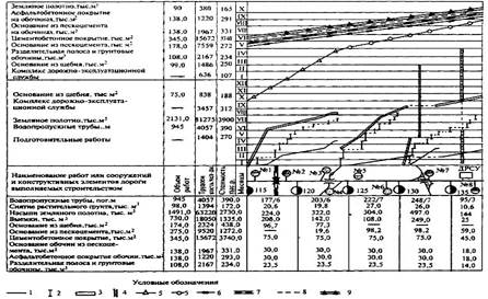
Rice. 2. Linear calendar schedule for organizing the construction of a highway:
1 - preparatory work; 2 - construction of culverts; 3 - construction of embankments and development of excavations; 4 - construction of a road maintenance service complex;
5 - construction of a base made of crushed stone and sand cement; 6 - arrangement of the base of the roadsides;
7 - installation of cement concrete covering; 8 - dividing strip device;
9 - installation of asphalt concrete roadside pavement
It should be borne in mind that the calendar schedule rigidly fixes one of many possible options construction. When deviations from the plan appear during the work, and this is inevitable, then reflect these changes on the schedule, i.e. It is very difficult to adjust it for a complex set of works; a complete rework of the schedule is often required. Therefore, the calendar schedule is characterized by low dynamism at the management stage, which often leads to its inconsistency with the actual production situation.
From the general complex of works reflected on the linear calendar chart, it is difficult to identify the most intense ones, focus the main attention on them, and also to estimate the values of the reserves of less intense work and determine the order of their use. IN modern conditions these shortcomings become especially noticeable. Due to the increased volume of construction work and limited time For their implementation, the identification of existing reserves and their proper use is of particular importance.
In the last 15 - 30 years, active search new methods of work planning, free from these shortcomings and allowing the use of the achievements of modern mathematics and computer technology. One such method is network planning.
The first experiments in introducing network planning in the USSR date back to 1962. Network planning and management systems (SMS) were successfully used in the construction of a number of industrial facilities (Burshtyn State District Power Plant and Lisichansk Chemical Plant). In road construction, SPUs were first introduced by the Moscow-Volgograd highway construction department in 1965. According to our and foreign press data, the total construction period of objects according to network schedules was reduced by an average of 15%.
Taking into account the economic effect obtained from the introduction of network planning in various sectors of the national economy, the Council of Ministers of the USSR adopted a special resolution No. 639 of August 16, 1966 “On measures to introduce network planning and management systems into the national economy based on complex network graphs,” which determined specific tasks and the main areas of application of network planning and management (NPC).
To better understand the essence of the SPU method and its main advantages, it is advisable to recall the basic concepts and terms used in network planning.
A network diagram is a logical-mathematical model of a certain process, presented in the form of events and activities.
An event is the moment at which some work begins or ends. It has no duration and does not consume resources. The very first event determines the moment the work begins, the last one determines its completion. These events are called the initial and final events. Due to the complexity of the road work complex, the overall network plan are obtained by “stitching together” private network plans, each of which is developed by competent performers of the corresponding specialty. “Stitching” is carried out according to so-called transition events.
Thus, a transition event is common to several networks and can simultaneously be the end event for one particular network plan and the start event for another.
During road works, transition events can often be the moments of acceptance and delivery of completed work at adjacent sections of a complex flow. Thus, when installing a cement concrete pavement on a bitumen-soil base in a private network graphics according to the structure of the base, there may be an event: “the base on the 1st capture is handed over.” On a private network plan for the installation of a cement concrete pavement, there may be an event: “the foundation on the 1st capture has been accepted.” Since these events are identical, both private network plans can be “stitched” based on a given transition event, forming a comprehensive network plan showing both the foundation work and the coating work.
Work is the activity of performers in the period of time between two adjacent events. Work is divided into the following types: a) “actual work”, characterized by resource consumption and time expenditure (transport, excavation work, quarrying, etc.); b) “waiting”, i.e. a process that requires time, but does not consume resources (formation of a coating, strengthening of cement soil or concrete, if not required additional measures care, etc.); c) “fictitious work” or “dependency” - work that does not consume resources and has no duration, a connection between two adjacent events. For example, when constructing a gravel pavement using the mixing method on a road, after the event “end of bitumen pouring,” the event “start of mixing” can immediately occur without a break in time and without any expenditure of resources between the mentioned events. Therefore, the connection of these events should be reflected in the network diagram as fictitious work.
Actual jobs are shown on the graph as solid lines with an arrow, and expectations and dependencies (fictitious jobs) are shown as dotted lines.
A path is a sequence of jobs, the end of each of which coincides with the beginning of the next one. A network diagram is a collection of multiple paths that begin at the initial event (the moment of the start of work) and end at the final event (the moment of completion of construction). The most important paths are those that have no reserves. They determine the duration of construction work and are called critical. There can be several critical paths on one network diagram.
Events and works are characterized quantitative estimates. Each job has a duration te ij, which is expressed in hours, shifts, days and is written above the job arrow.