What is a TV remote made of? Troubleshooting TV remote controls
I. Ivanov
You can check the operation of the remote control in the absence of a TV using an infrared photodiode (PD). Suitable, for example, domestic FD-8K. The outputs of the PD are connected to the ground and signal probes of the oscilloscope. The remote control is placed coaxially with the FD close to its window. Press any of the buttons on the remote control. In this case, a PWM signal with an amplitude of 0.2 ... 0.5 V should appear on the oscilloscope screen.
Most television remote control circuits are the same and include:
- a microcircuit-former of commands with a quartz resonator;
- an amplifier consisting of one or two transistors;
- LED (or two);
- keyboard and contact field.
In addition, some remote controls have an indicator LED that registers the command.
Consider possible malfunctions of the remote control, the method of their detection and elimination.
1. No signal from remote control
Check the condition of the batteries. If the supply voltage is less than 2.5 V, the batteries must be replaced. At a voltage greater than 2.5 V, check the short-circuit current Ikz with a multimeter. For serviceable elements, it should be equal to 1 ... 3 A. If IkzThen open the remote. This operation requires certain skills and accuracy. The main task in this case is not to leave scratches on the remote control case and not to break the latches. To open the remote control, use an ordinary screwdriver with a thin sting (currently, special screwdrivers with a sting 10 .... 20 mm wide and 0.5 mm thick with a short handle are on sale).
The remote control begins to be opened from the side where the batteries are located, and first one side of the bottom cover is disconnected to the entrance window, and then the other in the same way, after which the cover is easily removed.
Conduct an external inspection of the condition of the printed circuit board and keyboard contacts.
Traces of dried liquid on the contact field are removed with a cotton swab moistened with alcohol. Breaks in the conductors are eliminated by soldering jumpers made of thin wire.
Check for contact between graphite jumpers and printed conductors.
Having closed any pair of contacts on the printed circuit board, they check with an oscilloscope the presence of a PWM signal on the LED cathode.
If there is no signal, and the constant voltage is zero, check the continuity of the LED. For a working LED, the resistance in the forward direction should be several tens of ohms, and in the reverse direction - several hundred kilo-ohms. A defective LED must be replaced.
A fairly common defect is a break in the output of the LED as a result of mechanical stress, for example, after the remote control has been dropped.
Check the passage of the PWM signal from the output of the microcircuit to the LED.
2. There is no signal at the output of the remote control chip
lack of supply voltage of the microcircuit;
malfunction of the quartz resonator;
the presence of two or more pairs of closed contacts of the printed circuit board;
breakage of conductors between the microcircuit and the contacts of the printed circuit board;
microchip failure.
First, check the supply voltage of the microcircuit: it must be at least 2.5 V.
The performance of the quartz resonator is checked by closing any of the pairs of contacts on the printed circuit board. If there is no generation at the same time, then the microcircuit is most likely faulty.
3. There is no signal from the remote control. There is a signal at the output of the microcircuit
Possible causes of the malfunction:lack of power supply to the amplifier;
malfunction of the amplifier elements;
LED failure.
An oscilloscope checks for a signal at the cathode of the LED. If there is no signal here, check its passage from the output of the microcircuit to the LED.
The most common defects in this case are the failure of the transistor of the output stage of the amplifier, the violation of soldering, the conclusions of the amplifier elements.
4. There is no signal from the remote control. The photodiode indicates the presence of a constant voltage level. Batteries run out quickly. The LED is constantly on and a significant current flows through it
Possible reasons:breakdown of one of the transistors of the amplifier;
the presence of two or more pairs of closed keyboard contacts;
microchip failure.
The serviceability of transistors and the presence of closed contacts are checked by "dialing". The health of the microcircuit is checked by replacement.
5. A command is constantly sent from the remote control when the keyboard buttons are not pressed. Batteries drain quickly
Possible causes of the malfunction:reduction of insulation resistance between the pins of the microcircuit or the contacts of the printed circuit board;
reduction of insulation resistance between the graphite jumper and the printed conductor passing under it;
microchip failure.
The pins of the microcircuit are thoroughly washed with alcohol, eliminating traces of rosin, dust, and dirt. On the printed circuit board, wipe the contacts with a cotton swab moistened with alcohol. Solder the corresponding pins of the microcircuit from the board. If after that the commands from the remote control continue to arrive, the microcircuit is changed. If the signal disappears, look for a place of current leakage from the graphite jumper to the printed conductor. The conductor is cut off on both sides and a jumper from an insulated wire is placed (soldered) instead.
6. One or more remote control buttons do not work
Possible causes of the malfunction:increase in the resistance of the closing contacts of the keyboard;
board crack.
Measure the contact resistance with a multimeter. For serviceable buttons, it is 2 ... 5 kOhm. If the resistance is more than 10 kOhm, the button is faulty. In this case, either the "gum" is changed entirely, or the contact is repaired. Special repair kits for the remote control are available for sale. They consist of conductive rubber contacts that are glued to faulty keyboard contacts with silicone adhesive included in the repair kit.
The presence of cracks is determined visually. Damaged printed conductors are repaired using thin wire jumpers.
In most modern remote controls, it is possible to convert them into a service console. The essence of the alteration is to install a new jumper or rearrange the jumper on the printed circuit board, and the installation location on the board is indicated.
As an example, the figure shows the remote control RM-836 for SONY TVs with the top cover removed. After installing the jumper in pos. one

Changes the functionality of the aspect ratio button.

Now, after pressing this button twice, the TV is transferred from the operating mode to the service mode.
Repair of remote controls.
M. KireevAfter several years of operation, the functioning of remote controls (DU) of TVs and other equipment is often disrupted. This is possible for several reasons: violation of the integrity of the soldering of electronic components, oxidation of the spring contacts in the battery compartment, complete or partial abrasion of the conductive layer applied to the ends of the buttons (Fig. 1),

Which are the most commonly used.
To eliminate the last defect, a simple method is proposed that has been tested for several years and does not require large expenditures. On the cleaned and degreased, for example, with alcohol, the end of the button, the performance of which needs to be restored, is applied one layer of quick-drying glue, for example, "Second", and then a piece of aluminum foil is glued slightly larger than the area of the end of the button. After the glue has hardened, the protruding foil is carefully crimped with tweezers (Fig. 2).
Practice has shown high reliability and trouble-free operation of consoles repaired in this way.
If you often have to deal with the repair of remote controls, then you can make a device for monitoring their performance, assembled from available parts (Fig. 3).

Chip DA1 is used to amplify the signal coming from the infrared photodiode VD1, and the formation of a sequence of output pulses, which is fed to the divider DD1.1. When you press any button of a working remote control, the VD2 LED will flash at a frequency of several hertz. It is convenient to mount the device in a case measuring 100x40x30 mm (Fig. 4).

The DA1 chip can be replaced by domestic analogues KR1054UI1, KR1054XA3, KR1056UP1, KR1084UI1, taking into account the difference in pinouts.
Repair & Service
Etc. audio-video equipment).
Encyclopedic YouTube
-
1 / 5
One of the earliest examples of remote control devices was invented by Nikola Tesla in 1898. The mechanism has been patented and described in Method of and Apparatus for Controlling Mechanism of Moving Vehicle or Vehicles. In 1898, at an electrical exhibition in Madison Square Garden, he demonstrated to the public a radio-controlled boat called "teleautomatic".
The first TV remote control was developed by Eugene Polley, an employee of the American company Zenith Radio Corporation in the early 1950s. It was connected to the TV with a cable. In 1955, a wireless remote control was developed. Flashmatic, based on sending a beam of light in the direction of the photocell. Unfortunately, the photocell could not distinguish the light from the remote control from the light from other sources. In addition, it was required to point the remote control exactly at the receiver.
By the early 2000s, the number of household electrical appliances had increased dramatically. Five or six remotes may be required to control a home cinema: from a satellite receiver, a VCR, a DVD player, a television and an audio amplifier. Some of them need to be used one after the other, and due to the disparity of the control systems, this becomes burdensome. Many experts, including renowned usability expert Jakob Nielsen and inventor of the modern remote control, Robert Adler, have commented on how confusing and clumsy multiple remote controls are.
The advent of a PDA with an infrared port made it possible to create universal remote controls with programmable control. However, due to the high cost, this method has not become very common. Special universal learning control panels have not become widespread either due to the relative complexity of programming and use. It is also possible to use some mobile phones for remote control (via Bluetooth) of a personal computer.
Remote control types
Remote controls differ in:
Nutrition:
- autonomous;
- received by cable (wire).
Mobility:
- built-in (stationary);
- wearable.
Functionality:
- with a fixed set of commands;
- with switchable command set (universal);
- with instruction set training (teachable).
Communication channel:
- mechanical;
Application
Remote controls are used to remotely control consumer electronic equipment (TVs, music centers, audio and video players, etc.). Miniature remote controls have car alarms. There are remote controls for controlling robots, aircraft models, etc. Even temples are equipped with remote control systems. In general, the remote control can be used in any device that has electronic control.
Remote control for home appliances
A consumer electronics remote control is usually a small, button-operated, battery-powered device that sends commands via infrared radiation with a wavelength of 0.75-1.4 microns. This light is invisible to the human eye, but is recognized by the receiver of the receiving device. Most remote controls use a single dedicated chip, packaged or unpackaged (placed directly on the printed circuit board and filled with compound to prevent damage).
Previously, only the main functions of the device were placed on the remote control (channel switching, volume control, etc.), now most samples of modern consumer electronics on the case itself have a limited set of controls and a full set of them on the remote control.
For the first remotes to transmit one function, command (single-channel remote control, with one button), the presence / absence of the transmitted signal itself was enough. But even then only if it was transmitted over an interference-free channel (for example, a wire), otherwise external interference (rays of the Sun, etc.) led to a false alarm. The first wireless remote controls used an ultrasonic communication channel.
For consoles with several functions, a more complex system is needed - frequency modulation of the carrier signal (it is also used to create channel noise immunity) and coding of transmitted commands. Now digital processing is used for this - the transmitter microcircuit (in the remote control) modulates and encodes the transmitted signal, in the receiver it is demodulated and decoded. After demodulating the received signal, appropriate frequency filters are applied to separate the signals.
To read the code of the pressed button, the method of scanning the lines of the button matrix is \u200b\u200busually used (a similar method is used in computer keyboards), but in home appliance remote controls, using continuous scanning would require energy and the batteries would quickly run out. Therefore, in standby mode, all scan lines are set to the same state and the console processor is put into sleep mode, turning off the clock generator and practically consuming no energy. Pressing any button on the scan input lines changes the logic level, which causes the processor to wake up and start the clock generator. After that, a full keyboard scan cycle is launched to determine the button that caused the wake-up. The "one button - one line" method is usually not used due to the large number of buttons on modern remote controls. After determining the pressed button, the remote control generates a package containing the remote control code and the button code.
Household remote controls do not have feedback, which means that the remote control cannot determine whether the signal has reached the receiver or not. Therefore, the signal corresponding to the pressed button is transmitted continuously until the button is released. When the button is released, the remote control switches back to the standby state.
Data is received on the receiving side (for example, on a TV set): the remote control code is checked, and if this code matches the specified one, the command corresponding to the pressed button is executed. The transmitter and receiver (remote and unit) must use the same encoding methods and modulation frequency transmitted data, otherwise the receiver will be unable to receive and process the data sent to it.
Modulation
Typically, remotes use one carrier modulation frequency (that is, the frequency of the IR LED radiation) - both the remote and the receiver are configured for it. Modulation frequencies are usually standard - these are 36 kHz, 38 kHz, 40 kHz (Panasonic, Sony). Frequencies of 56 kHz (Sharp) are considered rare. Bang & Olufsen uses 455 kHz, which is very rare. Using a receiver with a modulation frequency that does not exactly match the frequency of the transmitter does not mean that it will not receive - reception will remain, but its sensitivity may drop very much.
Signal transmission is carried out by radiation of an IR LED with the corresponding modulation frequency. For frequencies from 30 to 50 kHz, LEDs with a wavelength of 950 nm are usually used, and for 455 kHz, special LEDs with a wavelength of 870 nm (dedicated receivers TSOP5700 and TSOP7000 are oriented to this wavelength and high modulation frequency).
Several such modulated transmissions and blankings ( bursts of impulses) form coded parcel(see below). The IR signal receiver consists of several stages of amplifiers and a demodulator (frequency detector) and is sensitive to a signal up to -90 dB (most amateur radio circuits have a sensitivity of up to -60 dB). Also, almost all mass-produced IR receivers have an IR light filter (dark red lens or plate). The IR receiver module itself has only three outputs: Food, Earth, data output.
Example photodetectors: TSOP1736 - tuned to 36 kHz, TSOP1738 - 38 kHz (manufacturer Vishay Telefunken), BRM1020 - 38 kHz.
To receive a signal from the remote control, there is also a demodulator without a built-in IR photodetector - a Sony CXA1511 chip, in essence, a high-quality frequency detector that allows you to make a remote control, for example, on UV emitters, and not on IR LEDs.Coding
To recognize many different remote control commands, encoding of the transmitted data is used. Currently, the following two coding schemes for transmitted data are mainly used:
- The first in remote controls was used by Philips (RC4 and RC5 protocols, the so-called Manchester coding): Transmission 0 was supplemented with a unit, and transmission 1 with a zero. That is, 001 is transmitted as 01 01 10. Accordingly, the package is read sequentially, and a modulated signal is sent on the air only when a unit is encountered.
- The authorship of the second coding scheme is attributed to Sony. First, a “1” is always transmitted in a modulated signal, then a “0” is a pause. The time dimension of one is always the same, and the time dimension of 0 is the encoded transmitted data. Long pause - transmission of one, short pause - transmission of zero.
Before sending encoded data, the remote control always sends one or more sync messages so that the photodetector sets up the receiving circuit (synchronizes with the remote control in sensitivity and phase).
- Protocols RC5, Sony SIRC, Panasonic, JVC, Daewoo
Remote control manufacturers are not inclined to adhere to any common standard data encoding protocols and have the right to develop and apply more and more new protocols for their equipment. A more complete list of protocols: NEC (repetitive pulse), NEC (repetitive data), RC5, RC6, RCMM, RECS-80, R-2000 (33 kHz), Thomson RCA (56.7 kHz), Toshiba Micom Format (similar NEC ), Sony 12 Bit, Sony 15 Bit, Sony 20 Bit, Kaseikyo Matsushita (36.7 kHz), Mitsubishi (38 kHz, preburst 8 ms, 16 bit), Ruwido r-map, Ruwido r-step, Continuous transmission 4000 bps and Continuous transmission 1000 bps.
Food
Household remote controls are usually powered by 2-4 size or AAA batteries (rarely by a 9 V Krona battery). This is due to the fact that at least 2.0-2.5 Volts are needed to power the infrared LED, and such a voltage cannot be obtained from one battery (1.5 V) without complicating the circuit. For remote controls, it is recommended to buy ordinary salt or alkaline (Alkaline) batteries, they will last longer - the fact is that similar (AA or AAA) batteries can be discharged in half a year only because of the high self-discharge current they have, besides a long period operating a single charge will not pay for the cost of the battery.
Wireless remote control problems
- dead batteries (the most common malfunction);
- the remote control is filled with some kind of liquid and the buttons either sink or do not release;
- the quartz resonator or IR LED fell off (or damaged) from the impact;
- from frequent use, the conductive coating on the buttons themselves (or the conductors under the buttons) wears out;
- dirt from hands that gets inside the remote control and accumulates over time.
The presence of a signal from the remote control can be checked by looking at it through a video camera or digital camera while pressing the buttons on the remote control. CCD sensors of household photo and video equipment usually see the infrared range.
It is also common to hear signals modulated by the remote's infrared carrier near a medium wave radio that is not tuned to a station.Almost every person has a bunch of different smart appliances at home - a variety of TVs, audio systems, CD players, air conditioners, washing machines, microwave ovens and much more. Most of these devices have remote controls. Remotes were once conceived to help people so that they could control all the electronics in their home from the comfort of their seats. However, sometimes there are so many assistants that finding the right one becomes a rather annoying problem. Fortunately, you can buy a universal remote control, and forever solve the inconvenience of controlling equipment. So, what should you pay attention to first of all when choosing a reliable universal remote control, so as not to regret the purchase and be satisfied.
Why you need a universal remote control
- One of the old ones is simply lost, or it has become unusable. Most of the time it's a TV remote. A person comes to the store, buys the most touted universal remote control, comes home, and ... He does not call up the menu on the TV, and the setting does not work. And the fact is that not everyone can be suitable for his TV.
- A person wants to have one remote control for all devices in the house. This is a completely different matter. Using native remotes, you can always set up a new remote control for any equipment, as long as it supports the learning function.
About the features of the universal remote control

- The universal preset remote control has a database with codes for various devices and models. When you need to control the fan, the user enters one code, when the TV - another. The codes are taken from the list provided by the manufacturer.
- Models with settings via a computer can be connected to a laptop or computer, and by managing special programs, download the necessary settings for your equipment from the manufacturer's server. This procedure is very similar to updating drivers on a computer's operating system. Just indicate the models of your equipment on the website, and save the settings offered to you on the remote control. Also on the website of the manufacturer of the universal remote control, before buying, you can see the list of brands of equipment with which it is compatible. In terms of a good price-quality ratio, among all the models on the market, remote controls in this category are most common.
- The learning model is a very handy gadget. Learning goes like this. You take your own remote control, and register the function of each button from it on the button of the universal one you need, and after a while it performs the functions better than the old one. It is very convenient if the manufacturer has not included signals for your TV (or any other device) of your brand in its database. It is worth noting that when choosing such a remote control, you need to pay attention to its signal range, check with the seller if necessary, or consult with a specialist. Since there are rare devices whose signals are not perceived by some devices with a learning function.
Which model to choose

On various thematic forums, you can find heated debates between adherents of one or another remote control model, since each device has its pros and cons. There you can also get advice on choosing a reliable universal remote control. There are remotes that combine all three types of models, they have a high rating in online stores, they are more expensive than all the others. Decide if you need one, or can just buy an inexpensive but good one.
Manufacturing firm

Some buyers choose a remote control based on the preference of devices from their favorite manufacturer. But to believe that a company that makes excellent washing machines makes high-quality remotes is a delusion. Some popular brands produce such devices that are not of special quality - "for show", simply dressing them in beautiful packaging. You should trust only those brands that have been manufacturing "universal cars" for a long time and professionally. They have a large database of codes for equipment, decent technical support and experienced specialists. The most popular manufacturers of control panels are:
- Philips
- Rolsen
Additional functionality

Each feature in the new model comes with a price. The more features, the more expensive it is. A small-functional, but cheap remote control may be the best solution for you if all your equipment is from the same manufacturer. However, the setting method is not the only selection criteria. Universal remote controls differ in the number of devices they can work with. So, if there are 15 devices in your house, and you buy a remote control to control eight, you will have to choose these 8 lucky ones.
Pay attention to such additional features as the possibility of reprogramming, various built-in macros. Sometimes remotes with the same price, unreasonably have completely different functionality. Few people think that their new toy may break, so take care of the availability of the device service in advance. It will be very disappointing if then there is no such or similar remote control in the store and you will scold yourself for short-sightedness while waiting for a replacement.
Appearance

The appearance of a modern universal remote control is very diverse. So the device can be:
- With keys. These are various buttons for changing the sound level, numbers with channel designations, paired channel switching keys, device settings buttons, and joysticks for moving through the menu of categories of controlled devices.
- With keys and screen. To the buttons of the models described above, a small screen is added, which displays the time, settings, room temperature and control operations. Such devices are more expensive.
- Touch. All buttons are software and interaction with the universal remote control takes place as in a modern smartphone. The most expensive models are not always convenient to use, and it is better to try switching them yourself when buying.
The most convenient for today in terms of all characteristics is the second option - with keys and a screen. All the actions performed are clearly visible on the screen, and you can always assign additional actions to the buttons and assign their own function to each. Or even assign a sequence of operations. Pay attention to what comes with the universal remote control, it is better if the kit includes a stand for it. These stands are often backlit and rechargeable.
Management problems
 Experts in installing and configuring home appliances, when consulting on the topic of a universal remote control, often warn of possible problems when setting up air conditioning control. If the remote control does not have the required code for a particular air conditioner, then nothing will come of it. This happens because the signals of the air conditioner remote control differ from the signals sent by other equipment (TVs, DVD players) to their remotes. The air conditioner has a different signal for each temperature level, so even learning a universal remote control will be a rather tedious task.
What to look for before buying

Carefully inspect your future purchase. Sometimes there may be too many keys on it, this will add inconvenience, and not at all opportunities. Good advice is how to choose a universal remote control, maybe check in a store, or even better at home. Perhaps there is a friend at work or a friend who has already purchased such a device. You can ask him to borrow the gadget for a while, for testing in real conditions.
Remember how in the cartoon “Three from Prostokvashino”, Uncle Fyodor’s mother said: “I get so tired at work that I can’t even watch TV!” Apparently, this phrase is the answer to the question why all modern household equipment has infrared remote controls (RC). But, if you look, it all started much earlier.
remote control with wires
The first works on remote control were carried out by the Germans in the late 30s of the twentieth century, even before the outbreak of World War II. The object of automation was a tube receiver. The control panel was a separate metal panel with buttons. Pressing the button led to the actuation of the actuator - relay, electromagnet or motor. The connection between such a remote control and the receiver was made with a multi-core cable, which still tied the listener to a certain place.
Soviet first-class tube TVs had similar remotes. It was a small plastic box with a volume control connected to the TV with a wire. In addition to the volume, such a remote control could not control anything. But such a remote control undoubtedly created certain conveniences. After all, then there was no annoying advertising and the film had to be watched from beginning to end.
Ultrasonic remote controls
The first wireless remote control owes its birth to the American Hasso Plattner. In 1972, after leaving IBM, he organized his own firm and traveled extensively around the world in order to establish business contacts and connections. At one of the meetings with the management of JVC, an embarrassing incident occurred.
When discussing some problem, Plattner stood up and moved to the TV to show some detail on the screen with his finger. But, he did not reach the screen, tripping over the remote control cable. He spilled a cocktail on the suit and said in his hearts: “Couldn’t you have switched channels by radio wave?”, which drove the Japanese companions into the paint. And exactly one year later, the first remote control on ultrasonic rays appeared.
The principle of its operation was to apply its own frequency when pressing each button. The ultrasound was picked up by a microphone and amplified by an amplifier that used several parallel channels with resonant circuits. Control voltages appeared at the outputs of these channels. With this method of encoding channels, not very much was obtained.
Further development of electronics, in particular the appearance of INTEL chips, made it possible to abandon such multi-frequency coding. At one ultrasonic frequency, due to various modulation methods, it became possible to transmit many more commands than with multi-frequency coding. One of the first devices equipped with an ultrasonic remote control was an RCA TV. Commands were coded using pulse-width modulation (PWM).
These remotes had a number of disadvantages. First of all, large dimensions and power consumption. This was due to the fact that ultrasonic radiation is readily absorbed by household items - clothing, upholstered furniture, carpets. Therefore, the radiation power needed to be increased, which reduced the battery life.


Rice. 1. The first remote controls
Specialized chips for remote control
Things got better after Intel developed its first microprocessor, the 8080. This new development was taken as a basis by GRUNDIG and MAGNAVOX, which made the first dedicated microprocessor. In this case, the processor generates the desired digital command code under the influence of the pressed button. Thus, a specialized microcircuit for the remote control is nothing more than with an already flashed program. Such remote controls were called TELEPILOT.
IR remote control
The first color television with microprocessor control and an IR remote control (RC) was released jointly by GRUNDIG and MAGNAVOX already in 1974. Already in this model, the number of the switching channel was shown in the corner of the screen (OSD system). This command system was called ITT. It was the first-born of the GRUNDIG company.
In the future, research in the field of remote control was taken up by PHILIPS, which developed the RC-5 command system. The new system allowed 2048 commands to be encoded, which was 4 times the number of commands in the ITT system. The carrier frequency was chosen to be 36 kHz, which did not interfere with the transmissions of European broadcasting stations and the operation of consoles with ultrasonic transmitters with a frequency of 30 and 40 kHz, and also provided a sufficient reception range.
But electronic technology did not stand still, but as one movie hero said, it went forward with leaps and bounds. TVs were improved, VCRs and stereos, satellite tuners, CD and DVD players, and much more appeared.
To control the new equipment, new remote controls were also required, and, accordingly, new microcircuits had to be developed. Such microcircuits were developed by SIEMENS and THOMSON. The carrier frequency of the new remote controls was also 36 kHz, but a different method of signal modulation was used - two-phase modulation. With such modulation, the carrier frequency was more stable, which ensured an increase in range, an increase in noise immunity and reliability.
PHILIPS again made a further contribution to the development of remote control systems. At the beginning of the 90s of the last century, it combined all the best that was in the RC-5 and SIEMENS systems. The resulting product was called the Unified Command System. Its essence is as follows. The remote controls of such a system have the "MENU 1" and "MENU 2" functions. In each of these functions, the same button performs different commands, and it turns out that with fewer buttons, more commands can be performed.
Subsequently, control panels penetrated into many other areas of household appliances. IR radiation currently controls air conditioners, fans, wall fan heaters, . Even some models of car radios and digital cameras have a remote control.
With all the variety of remotes and devices controlled by them, they all work almost the same: when the buttons are pressed, the infrared LED of the remote control emits bursts of infrared pulses (flashes), which are received by the photodetector ("eye") of the TV or other device. A modern integrated photodetector is a rather complicated device, although this cannot be said from its appearance. The appearance of the photodetector is shown in Figure 2.

Figure 2. Photodetector
The receiver is configured to receive pulses with a carrier frequency of 36 kHz, which corresponds to the RC-5 protocol. If you simply turn on an IR LED near the photodetector, for example, from a battery, then its unblinking glow will not have any effect on the “eye”, even if this LED is brought close to the photodetector. It is also unaffected by daylight and artificial light. Such selectivity is due to the fact that there is a band-pass filter in the signal amplification circuit of the photodetector. The block diagram of the photodetector is shown in Figure 3.
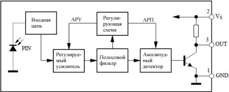
Figure 3. Structural diagram of a photodetector
The RC-5 protocol will not be explained in detail here, since this ignorance will not affect the further story, and actually the repair of the remote control, in any way. Those who wish to get acquainted with the RC-5 protocol in more detail can find its description on the Internet. This is a topic for a separate article.
Remote control device
With all the variety of modern remote controls, all models are arranged almost the same. The main difference is most often in the appearance, in the design of the device. As mentioned in the first part of the article, the basis of a modern remote control is a specialized microcontroller. The program in the MK is recorded during the manufacturing process at the factory and cannot be changed in the future. When included in the circuit for such an MK, a minimum number of attachments is required. A diagram of a modern remote control is shown in Figure 4.

Figure 4. Scheme of a modern remote control
The basis of the entire device is a U1 chip of type SAA3010P. Although the letters may be different, which indicates a different microcircuit manufacturer. But the numbers still remain 3010.
As mentioned above, there are practically no attachments. First of all, it is, although this is not entirely accurate. Its purpose is to synchronize the internal oscillator of the microcircuit, which provides the required temporal characteristics of the output signal.
The KEY MATRIX is shown in the lower right corner of the diagram. Its rows are connected to pins DR0…DR7, and columns, respectively, to pins X0…X7. When any button is pressed, one column-row pair is closed, and a pulse sequence corresponding to the pressed button appears at the output of the microcircuit. Each button gives out its own sequence and no other! In total, it is possible to connect 8 * 8 = 64 buttons, although in practice it may be less.
The output signal in the form of voltage pulses is fed to the gate of the field-effect transistor VT1, which in turn controls the operation of the IR LED VD1. The control algorithm in this case is very simple: the transistor opens - the LED lights up, the transistor is closed, the LED goes out. In this case, they say that the transistor operates in the key mode. As a result of such flashes, pulse packets are formed that correspond to the RC-5 control protocol.
The circuit is powered by two AA type galvanic cells, the energy of which is enough for at least a year. In parallel with the batteries, there is an electrolytic capacitor C1, which, by shunting the internal resistance of the batteries, prolongs their service life and ensures the normal operation of the remote control when the batteries are somewhat “run down”. An LED in pulse mode can consume current up to 1A.
After considering the remote control circuit, it seems that we can say that there is absolutely nothing to break with such a simple device, but this is not so. It is the remote control that most often causes trouble to the owner of the TV. How to repair the remote control, what are its main "diseases", as well as how and how to cure them will be described in the second part of the article.
A consumer electronics remote control is usually a small, button-operated, battery-powered device that sends commands via infrared radiation at a wavelength of 0.75-1.4 microns. This spectrum is invisible to the human eye, but is recognized by the receiver of the receiving device. Most remote controllers use one specialized quartz-resonator command-shaper chip, packaged or unpackaged (placed directly on the printed circuit board and filled with compound to prevent damage), a signal amplifier consisting of one or two transistors, and an emitting diode (or two) IR range. Additionally, in some remote controls, an LED is also installed to indicate the sending of commands.


Scheme of the EUR51971 remote control for TV.

Schematic of the IP-Q console 1 on chip SAA /7 with its command protocol (number 448), developed byThomson with the assistance of Philips, these TVs can be classified as Saba T6301/FF345. TC342/365/440/460, Telefunken Chassis 418A, FB-180, Thomson Chassis ICC7.
All over the world, the RC-5 remote control system is most widely used for household radio equipment. This system was developed by Philips for the needs of controlling household equipment and is used in many televisions. For remote controls, a specialized transmitter chip is available SAA3010 ( PO "Integral" produces an analogue INA3010 ). The use of a dedicated transmitter chip drastically reduces the required number of components and allows the IR transmitter to be placed in a small package. In addition, these microcircuits solve the issue of low consumption in standby mode, which makes the operation of the remote control very convenient: there is no need for a separate power switch. The circuit enters the active mode when any button is pressed and returns to the modemicroconsumptionswhen she is released. Currently, different manufacturers produce a large number of modifications of the RC-5 remote controls, and some models have quite a decent design. Industrial remotes are usually designed to control TVs. Therefore, they use system 0 of the RC-5 code. It is quite easy to switch to another system number, and then the mutual influence of different remotes will be excluded.When we press a button on the remote control, the transmitter chip is activated and generates a sequence of pulses that have a fill frequency of 36 kHz. LEDs convert these signals into infrared radiation. The emitted signal is received by a photodiode, which again converts the IR radiation into electrical impulses. These pulses are amplified and demodulated by the receiver chip. Then they are fed to the decoder. Decoding is usually done in software by a microcontroller. RC5 code supports 2048 commands. These teams make up 32 groups (systems) of 64 teams each. Each system is used to control a specific device such as a TV, VCR, etc. One of the most common transmitter ICs is the SAA3010 IC. The SAA3010 transmitter chip allows +5V power supply.
· Supply voltage - 2...7V
· Current consumption in standby mode - no more than 10 μA
· Maximum output current - ±10 mA
· Maximum clock frequency - 450 kHz
The block diagram of the SAA3010 chip is shown in Figure 1.

Figure 1. Structure of the SAA3010 IC.
The description of the pins of the SAA3010 chip is given in the table:
Designation
Button Matrix Input Lines
Operation mode selection input
Button Matrix Input Lines
Modulated output
Output
Scan Outputs
Scan Outputs
Generator input
Test input 2
Test input 1
Button Matrix Input Lines
Supply voltage
The transmitter chip is the heart of the remote control. In practice, the same remote can be used to control multiple devices. The chip can address 32 systems in two different modes: combined mode and single system mode. In combined mode, the system is selected first, and then the command. The number of the selected system (address code) is stored in a special register and the command related to this system is transmitted. Thus, to transmit any command, successive pressing of two buttons is required. This is not very convenient and is justified only when working simultaneously with a large number of systems. In practice, the transmitter is more often used in single system mode. In this case, instead of the matrix of system selection buttons, a jumper is mounted, which determines the system number. In this mode, only one button press is required to send any command. Using the switch, you can work with several systems. And in this case, only one button press is required to transmit the command. The transmitted command will refer to the system currently selected with the switch.
To enable the combined mode, the output of the transmitter SSM (Single System Mode) must be applied low. In this mode, the transmitter chip operates as follows: during rest, the X and Z lines of the transmitter are driven high by internal p-channel pull-up transistors. When a button is pressed in an X-DR or Z-DR matrix, the keyboard debounce cycle is initiated. If the button is closed for 18 cycles, the "generator enable" signal is fixed. At the end of the debounce cycle, the DR outputs are turned off and two scan cycles are started, turning on each DR output in turn. In the first scan cycle, the Z-address is found, in the second - the X-address. When the Z-entry (system matrix) or the X-entry (instruction matrix) is found to be in the zero state, the address is latched. When a button is pressed in the system matrix, the last command (i.e., all command bits are one) is transmitted in the selected system. This command is transmitted until the system select button is released. When a button is pressed in the command matrix, the command is transmitted along with the system address stored in the latch register. If the button is released before transmission starts, a reset occurs. If the transfer has started, then regardless of the state of the button, it will be completed completely. If more than one Z or X button is pressed at the same time, the generator will not start.
To enable single system mode, the SSM pin must be high and the system address must be set with the appropriate jumper or switch. In this mode, the transmitter X-lines are in a high state during rest. At the same time, the Z-lines are turned off to prevent current consumption. In the first of two scans, the system address is determined and stored in a latch. In the second cycle, the command number is determined. This command is sent along with the system address stored in a latch. If there is no Z-DR jumper, then no codes are transmitted.
If the button was released between sending the code, then a reset occurs. If the button is released during the debounce routine or during the sensor scan, but before a button press is detected, then a reset also occurs. Outputs DR0 - DR7 have an open drain, at rest the transistors are open.
The RC-5 code has an additional control bit that is inverted each time the button is released. This bit informs the decoder whether the button is being held or a new press has occurred. The control bit is inverted only after a fully completed send. Scanning cycles are performed before each message, so even if you change the pressed button to another during the transmission of the package, the system number and commands will still be transmitted correctly.
The OSC pin is the input/output of a 1-pin oscillator and is designed to connect a ceramic resonator at a frequency of 432 kHz. In series with the resonator, it is recommended to include a resistor with a resistance of 6.8 Kom.
Test inputs TP1 and TP2 must be connected to ground during normal operation. A high logic level on TP1 increases the scan frequency, and a high level on TP2 increases the frequency of the shift register.
At rest, the DATA and MDATA outputs are in the Z-state. The pulse train generated by the transmitter at the MDATA output has a duty cycle of 36 kHz (1/12 of the clock frequency) with a duty cycle of 25%. The DATA output generates the same sequence, but without padding. This output is used when the transmitter chip acts as a built-in keyboard controller. The signal at the DATA output is completely identical to the signal at the output of the remote control receiver chip (but, unlike the receiver, it has no inversion). Both of these signals can be processed by the same decoder.
The transmitter generates a 14-bit data word, the format of which is:
· 2 start bits.
· 1 control bit.
· 5 bits of the system address.
· 6 command bits.

Figure 2. Data word format of the RC-5 code.
The start bits are for setting the AGC in the receiver IC. The control bit is a sign of a new press. The clock duration is 1.778 ms. As long as the button remains pressed, the data word is transmitted at 64 clock intervals, i.e. 113.778 ms (Fig. 2). To ensure good noise immunity, two-phase coding is used (Fig. 3).

Figure 3. Coding "0" and "1" in the RC-5 code.
When using the RC-5 code, it may be necessary to calculate the average current draw. This is quite easy to do if you use Fig. 4, which shows the detailed structure of the package.

Figure 4. Detailed structure of the RC-5 package.
To ensure that the equipment responds equally to RC-5 commands, the codes are distributed in a very specific way. This standardization allows you to design transmitters that allow you to control various devices. With the same command codes for the same functions in different devices, a transmitter with a relatively small number of buttons can simultaneously control, for example, audio complex, TV and VCR.
System numbers for some household appliances are listed below:
0 - TV
2 - Teletext
3 - Video data
4 - Video player (VLP)
5 - Video Cassette Recorder (VCR)
8 - Video tuner (Sat.TV)
9 - Camcorder
16 - Audio preamplifier
17 - Tuner
18 - Tape recorder
20 - Compact player (CD)
21 - Turntable (LP)
29 - LightingThe remaining system numbers are reserved for future standardization or experimental use. The correspondence of some command codes and functions has also been standardized.
Command codes for some functions are given below:
0-9 - Numerical values 0-9
12 - Standby mode
15 - Display
13-mute
16 - volume +
17 - volume -
30 - search ahead
31 - search back
45 - ejection
48 - pause
50 - rewind
51 - fast forward
53 - playback
54 - stop
55 - recordIn order to get a complete IR remote control based on the transmitter chip, you also need an LED driver that is capable of providing a large pulse current. Modern LEDs operate in remote controls at pulsed currents of about 1A.
It is very convenient to build an LED driver on a low-threshold (logic level) MOSFET, for example, KP505A.
An example of a circuit diagram of the console is shown in fig. 5.

Figure 5. Schematic diagram of the RC-5 console.
The system number is set by a jumper between pins Zi and DRj .
The system number in this case will be as follows: SYS = 8i + j
The command code that will be transmitted when pressing the button that closes line Xi with line DRj is calculated as follows: COM = 8i + j
Common faults.
Wireless remote control problems
- dead batteries (the most common malfunction);
- the remote control is filled with some kind of liquid and the buttons either sink or do not release;
- the quartz resonator or IR LED fell off (or damaged) from the impact;
- from frequent use, the conductive coating on the buttons themselves (or the conductors under the buttons) wears out;
- dirt from hands that gets inside the remote control and accumulates over time.
There is no signal from the remote control.
First, check the health of the batteries. If the voltage on the element is less than 1.3V, it must be replaced. An ammeter measures the "short circuit" current of the element. If it is less than 300 mA, the element must also be replaced.
You can check the operability of the remote control with any photodiode in the IR range. Under the action of IR radiation, a voltage appears at the terminals of the photodiode, which is recorded by an oscilloscope. The photodiode is placed opposite the remote control window. When you press the remote control buttons on the oscilloscope, pulses with a swing of 0.2 ... 0.5V should appear.
Checking the remote control without special tools.
You can, turn on the receiver to the "AM" range and by pressing the button on the remote control, bring it close to the receiver, sounds (pulse packets) will be clearly heard from the speaker
Another simple way to check if the remote control works is as follows: turn on the camera on the mobile phone, point the remote control at the camera and press any button, if the remote control is working, the infrared emitter will be visible on the phone display.If there is no signal, the remote control is defective. It is opened. This operation requires some skill and care so as not to leave scratches on the case and break the latches.
The printed circuit board is inspected, and the keyboard contacts traces of the dried liquid in the form of a whitish coating are removed from the printed circuit board and the contact field with a cotton swab moistened with alcohol. Cracks in the printed conductors are eliminated by soldering tinned wire jumpers on top.
They control the quality of soldering, and the absence of breakage in the leads of parts, first of all, this concerns the emitting IR diode and the quartz resonator. Then check the modes of operation.
Measure the supply voltage (usually + 3V) on the chip. An oscilloscope controls the operation of the generator when a pair of button contacts is closed. If there is no generation, check the constant voltage +1 ... 1.5V on the quartz resonator. If there is voltage, replace the resonators. In the absence of a constant voltage, the health of the microcircuit is checked (by replacement).
In the presence of generation, the following malfunctions are possible:
1. The appearance of a leak in one of the pairs of keyboard contacts. Check with an ohmmeter. The resistance between the contacts of a working pair must be at least 100 kOhm. Otherwise, the contacts are wiped with a cotton swab moistened with alcohol.
2. There is a leak from the graphite jumpers to the printed conductors passing under the jumpers. To troubleshoot, the microcircuit leads connected to the keyboard contacts are alternately soldered. If the generation stops when tapping the next output, check the circuits suitable for this output. The printed conductor under the graphite jumper is cut off on both sides and restored with a piece of insulated wire.
3. Penetration of dust, dirt, tin particles and rosin between the pins of the microcircuit. With a brush with a hard bristle and alcohol, the board is washed between the terminals.
4. Chip defect. If, after soldering its conclusions, the resistance of a pair of contacts has increased to normal, the microcircuit is faulty. It needs to be replaced.
There is no signal from the remote control, there is a pulse signal at the output of the microcircuit.
1. There is no power supply to the amplifier.
2. One of the amplifier transistors or the IR diode is faulty.
Troubleshooting begins with an oscilloscope checking for the presence of a pulse signal at the cathode of the IR radiation diode. If there is no signal, and the DC voltage is zero, check the condition of the diode. If it is working, and there is a constant voltage, but there is no signal, they check the signal from the output of the microcircuit to the IR radiation diode, the serviceability of the transistors, and the presence of supply voltage.
The most common defects are: a malfunction of the output transistor of the amplifier, a violation of the soldering of the leads of the elements.
There is no signal from the remote control. There is a constant voltage across the IR emitting diode. Batteries are discharging quickly.
The nature of the malfunction indicates that the IR diode is constantly open, a significant current flows through it, leading to the discharge of the elements.
Possible causes of the malfunction:
Breakdown of one of the transistors of the amplifier. Check with an ohmmeter.
The presence of two or more pairs of closed keyboard contacts. Check with an ohmmeter.
Defective chip. Check by replacement.
When the keyboard buttons are not pressed, a command is constantly received from the remote control.
Possible causes of the malfunction:
1. Reducing the insulation resistance between the pins of the microcircuit or the contacts of the contact field. Eliminate by washing with alcohol.
2. Leakage from the graphite bridge to the printed conductor passing under it. A defective conductor is cut off at both ends and a piece of insulated wire is soldered on top.
3. Defective chip. Check by replacement.
One or more commands are not received from the remote control.
The cause of the defect may be an increase in the resistance of the closing contacts of the keyboard, dirt on the contact field, cracks on the board, or a malfunction of the microcircuit.
An ohmmeter checks the resistance of contacts made of conductive rubber on the keyboard. For good contacts, it should be in the range from 2 to 5 kOhm. If the resistance exceeds 10kΩ, the contacts are faulty. Before changing the "rubber" entirely, you can try to restore faulty contacts. To do this, the rubber keyboard is first cleaned of dirt, for which it is washed under running hot water with soap and a brush. Then the faulty contact is applied to a sheet of writing paper and with little effort is passed over it. Due to the roughness of the paper, a thin layer of dirt and oxides is removed from the contact. Use of fine-grained emery paper is possible.
Another way to restore working capacity is to stick circles of conductive rubber on faulty contacts. They are included in special repair kits for the remote control, which are commercially available. Good results are obtained by gluing metal foil circles (from cigarettes). The paper-based foil provides a secure adhesive bond to the rubber. Breaks in the conductors are eliminated by soldering jumpers. Cracks in the contact area are repaired by applying a layer of conductive adhesive (commercially available).
The remote control emits a command, but the TV does not respond to it. TV is correct.
Possible causes of the malfunction: a defect in the quartz resonator or microcircuit.
Check by replacement.
Common ICsP DU
8U5800
M3005A8
M708
RC005HC
SAF1039
U327
With LA 3117
M3006LAB
M709
SAA1 124
SKC5401
UM400
DMC6003
М50115
M710
SAA1 250
SL490
MPD660
DYC-R02
М50119
MS144105
SAA3004
SN76881
IX0733PA
M50460
MS14497
SAA3006
STV3021
KS51800
М50461
MN6027
SAA3007
Т8909
KS51810
М50462
MN6030B
SAA3008
Т8813
LC7462
М50560
NEC1986
SAA3010
TC9012F-011
M3004AB
N58484P
PCA8521
SM3021
U321
Story
One of the earliest remote control devices was invented and patented by Nikola Tesla in 1893.
In 1903, the Spanish engineer and mathematician Leonardo Torres Quevedo introduced the Telekino at the Paris Academy of Sciences, a device that was a robot that carried out commands transmitted by electromagnetic waves.
 Remote control Zenith Space Commander 500, 1958
The first TV remote control was developed by the American company Zenith Radio Corporation in the early 1950s. It was connected to the TV with a cable. In 1955, the Flashmatic wireless remote control was developed, based on sending a beam of light in the direction of a photocell. Unfortunately, the photocell could not distinguish the light from the remote control from the light from other sources. In addition, it was required to point the remote control exactly at the receiver.
 Zenith Space Commander 600 remote control
In 1956, Austrian-American Robert Adler developed the wireless Zenith Space Commander. It was mechanical and used ultrasound to set the channel and volume. When the user pressed the button, it would click and hit the plate. Each plate extracted noise at a different frequency, and the TV's circuitry recognized that noise. The invention of the transistor made it possible to produce cheap electric consoles that contain a piezoelectric crystal that is powered by an electric current and oscillates at a frequency that exceeds the upper limit of human hearing (although audible to dogs). The receiver contained a microphone connected to a circuit tuned to the same frequency. Some of the problems with this method were that the receiver could be triggered by natural noise and that some people could hear piercing ultrasonic signals.In 1974, GRUNDIG and MAGNAVOX produced the first color TV with an IR control microprocessor. The TV had an on-screen display (OSD) - the channel numbers were displayed in the corner of the screen.
The impetus for more sophisticated types of remote control came in the late 1970s with the development of teletext by the BBC. Most remote controls sold at that time had a limited set of functions, sometimes only four: next channel, previous channel, increase or decrease the volume. These consoles did not meet the needs of teletext, where the pages were numbered with three-digit numbers. The remote to select the teletext page had to have buttons for numbers from 0 to 9, other control buttons, for example, to switch between text and image, as well as regular TV buttons for volume, channels, brightness, color. The first teletext televisions had wired remotes for selecting teletext pages, but the rise of teletext usage showed the need for wireless devices. And BBC engineers began negotiations with TV manufacturers, which led in 1977-1978 to the appearance of prototypes that had a much larger set of functions. One of the companies was ITT, and the infrared communication protocol was later named after it.
In the 1980s, Steven Wozniak of Apple founded CL9. The company's goal was to create a remote control that could control multiple electronic devices. In the fall of 1987, the CORE module was introduced. Its advantage was the ability to "learn" signals from different devices. He also had the ability to perform certain functions at the appointed time thanks to the built-in clock. It was also the first console that could be connected to a computer and loaded with updated software code. CORE didn't have much of an impact on the market. It was too difficult for the average user to program it, but it received rave reviews from people who were able to figure out its programming. These obstacles led to the dissolution of CL9, but one of its employees continued the business under the Celadon brand.
By the early 2000s, the number of household electrical appliances had increased dramatically. To control a home theater, five or six remotes may be required: from a satellite receiver, a VCR, a DVD player, a television and an audio amplifier. Some of them need to be used one after the other, and due to the disparity of the control systems, this becomes burdensome. Many experts, including renowned usability expert Jakob Nielsen and inventor of the modern remote control, Robert Adler, have commented on how confusing and clumsy multiple remote controls are.
The appearance of a PDA with an infrared port made it possible to create universal remote controls with programmable control. However, due to the high cost, this method has not become very common. Special universal learning control panels have not become widespread either due to the relative complexity of programming and use.
Sources.


