Parallel and series connection of resistors. Parallel connection
Details Category: Articles Created: 09/06/2017 19:48How to connect several lamps in a dollhouse
When you think about how to make lighting in a dollhouse or roombox, where there is not one, but several lamps, the question arises of how to connect them and network them. There are two types of connections: serial and parallel, which we heard about from school. We will consider them in this article.
I will try to describe everything in simple, accessible language, so that everything is understandable even to the most humanists who are not familiar with electrical intricacies.
Note: In this article we will only consider a circuit with incandescent light bulbs. Lighting with diodes is more complex and will be discussed in another article.
For understanding, each diagram will be accompanied by a drawing and next to the drawing an electrical wiring diagram.
First, let's look at the symbols on electrical circuits.
| Item name | Symbol on the diagram | Image |
| battery/battery | ||
| switch | ||
| wire | ||
| crossing of wires (without connection) | ||
| connecting wires (soldering, twisting) | ||
| incandescent lamp | ||
| faulty lamp | ||
| broken lamp | ||
| burning lamp |
As already mentioned, there are two main types of connections: serial and parallel. There is also a third, mixed: series-parallel, combining both. Let's start with the sequential one, as it is simpler.
Serial connection
It looks like this.

The light bulbs are placed one after the other, as if holding hands in a round dance. Old Soviet garlands were made according to this principle.
Advantages- ease of connection.
Flaws- if at least one light bulb burns out, the entire circuit will not work.

You will have to go through and check each light bulb to find the faulty one. This can be tedious with a large number of bulbs. Also, the light bulbs must be of the same type: voltage, power.
With this type of connection, the voltages of the light bulbs are added. The voltage is indicated by the letter U, measured in volts V. The voltage of the power supply must be equal to the sum of the voltages of all the bulbs in the circuit.
Example No. 1: you want to connect 3 1.5V light bulbs in a series circuit. The power source voltage required for the operation of such a circuit is 1.5+1.5+1.5=4.5V.
Regular AA batteries have a voltage of 1.5V. To get a voltage of 4.5V from them, they also need to be connected in a series circuit, their voltages will add up.
Read more about how to choose a power source in this article.

Example #2: you want to connect 6V bulbs to a 12V power source. 6+6=12v. You can connect 2 of these bulbs.
Example #3: you want to connect 2 3V light bulbs in a circuit. 3+3=6V. A 6 V power supply is required.
To summarize: serial connection is easy to manufacture; you need bulbs of the same type. Disadvantages: if one bulb fails, all of them do not light up. You can only turn the circuit on and off as a whole.
Based on this, to illuminate a dollhouse, it is advisable to connect no more than 2-3 light bulbs in series. For example, in sconces. To connect a larger number of light bulbs, you need to use a different type of connection - parallel.
Read also articles on the topic:
- Review of miniature incandescent lamps
- Diodes or incandescent lamps
Parallel connection of light bulbs
This is what a parallel connection of light bulbs looks like.

In this type of connection, all bulbs and the power supply have the same voltage. That is, with a 12v power source, each of the bulbs must also have a voltage of 12V. And the number of light bulbs may vary. And if, for example, you have 6V light bulbs, then you need to take a 6V power source.

When one bulb fails, the others continue to burn.

The light bulbs can be turned on independently of each other. To do this, you need to install your own switch for each.

Electrical appliances in our city apartments are connected according to this principle. All devices have the same voltage 220V, they can be turned on and off independently of each other, the power of electrical devices can be different.
Conclusion: When there are many lamps in a dollhouse, parallel connection is optimal, although it is a little more complicated than serial connection.
Let's consider another type of connection, combining serial and parallel.
Combined connection
An example of a combined connection.

Three series circuits connected in parallel
Here's another option:

Three parallel circuits connected in series.
Sections of such a circuit connected in series behave like a series connection. And parallel sections are like a parallel connection.
Example

With such a scheme, the burnout of one light bulb will disable the entire section connected in series, and the other two series circuits will remain operational.
Accordingly, sections can be turned on and off independently of each other. To do this, each series circuit needs to have its own switch.

But you can't turn on just one light bulb.
With a parallel-series connection, if one light bulb fails, the circuit will behave like this:

And if there is a violation in a sequential section like this:

Example:

There are 6 3V bulbs connected in 3 series circuits of 2 bulbs each. The circuits, in turn, are connected in parallel. We divide it into 3 consecutive sections and calculate this section.

In the series section, the voltages of the light bulbs add up, 3v+3V=6V. Each series circuit has a voltage of 6V. Since the circuits are connected in parallel, their voltage does not add up, which means we need a 6V power source.
Example

We have 6 6V bulbs. The light bulbs are connected in groups of 3 in a parallel circuit, and the circuits, in turn, are connected in series. We divide the system into three parallel circuits.

In one parallel circuit, the voltage for each light bulb is 6V, since the voltage does not add up, then the voltage for the entire circuit is 6V. And the circuits themselves are already connected in series and their voltages are already added up. It turns out 6V+6V=12V. This means you need a 12V power source.
Example
For dollhouses, you can use this mixed connection.
Let's say there is one lamp in each room, all lamps are connected in parallel. But the lamps themselves have a different number of light bulbs: two have one light bulb each, there is a two-arm sconce made of two light bulbs and a three-arm chandelier. In a chandelier and sconce, the light bulbs are connected in series.

Each lamp has its own switch. Power supply 12V voltage. Single light bulbs connected in parallel must have a voltage of 12V. And for those connected in series, the voltage is added to the section of the circuit
. Accordingly, for a sconce section of two light bulbs, divide 12V (total voltage) by 2 (the number of light bulbs), we get 6V (voltage of one light bulb).
For the chandelier section 12V:3=4V (voltage of one chandelier bulb).
You should not connect more than three light bulbs in one lamp in series.
Now you have learned all the tricks of connecting incandescent light bulbs in different ways. And I think that it won’t be difficult to make lighting in a dollhouse with many light bulbs, of any complexity. If something else is difficult for you, read the article about the simplest way to make light in a dollhouse, the most basic principles. Good luck!
Conductor resistance. Parallel and series connection of conductors.
Electrical resistance- a physical quantity that characterizes the properties of a conductor to prevent the passage of electric current and is equal to the ratio of the voltage at the ends of the conductor to the strength of the current flowing through it. Resistance for alternating current circuits and for alternating electromagnetic fields is described by the concepts of impedance and characteristic impedance. Resistance (resistor) is also called a radio component designed to introduce active resistance into electrical circuits.
Resistance (often symbolized by the letter R or r) is considered, within certain limits, a constant value for a given conductor; it can be calculated as
R- resistance;
U- electrical potential difference (voltage) at the ends of the conductor;
I- the strength of the current flowing between the ends of the conductor under the influence of a potential difference.
For serial connection conductors (Fig. 1.9.1), the current strength in all conductors is the same:
According to Ohm's law, voltage U 1 and U 2 on the conductors are equal
In a series connection, the total resistance of the circuit is equal to the sum of the resistances of the individual conductors.
This result is valid for any number of conductors connected in series.
In parallel connection (Fig. 1.9.2) voltage U 1 and U 2 on both conductors are the same:
This result follows from the fact that at current branching points (nodes A And B) charges cannot accumulate in a DC circuit. For example, to the node A in time Δ t charge is leaking IΔ t, and the charge flows away from the node at the same time I 1Δ t + I 2Δ t. Hence, I = I 1 + I 2 .
Writing based on Ohm's law
When connecting conductors in parallel, the reciprocal of the total resistance of the circuit is equal to the sum of the reciprocals of the resistances of parallel-connected conductors.
This result is valid for any number of conductors connected in parallel.
Formulas for series and parallel connection of conductors allow in many cases to calculate the resistance of a complex circuit consisting of many resistors. In Fig. 1.9.3 shows an example of such a complex circuit and indicates the sequence of calculations.
It should be noted that not all complex circuits consisting of conductors with different resistances can be calculated using formulas for series and parallel connections. In Fig. 1.9.4 shows an example of an electrical circuit that cannot be calculated using the above method.
Series connection of resistances
Let's take three constant resistances R1, R2 and R3 and connect them to the circuit so that the end of the first resistance R1 is connected to the beginning of the second resistance R2, the end of the second is connected to the beginning of the third R3, and we connect conductors to the beginning of the first resistance and to the end of the third from the current source (Fig. 1).
This connection of resistances is called alternating. Of course, the current in such a circuit will be the same at all its points.

Rice 1. Series connection of resistances
How to find the total resistance of a circuit if we already know all the resistances included in it one by one? Using the position that the voltage U at the terminals of the current source is equal to the sum of the voltage drops in the sections of the circuit, we can write:
U = U1 + U2 + U3
Where
U1 = IR1 U2 = IR2 and U3 = IR3
or
IR = IR1 + IR2 + IR3
Taking the equality I out of brackets on the right side, we obtain IR = I(R1 + R2 + R3) .
Now dividing both sides of the equality by I, we will have R = R1 + R2 + R3
Thus, we concluded that when resistances are alternately connected, the total resistance of the entire circuit is equal to the sum of the resistances of the individual sections.
Let's check this conclusion using the following example. Let's take three constant resistances, the values of which are known (for example, R1 == 10 Ohms, R 2 = 20 Ohms and R 3 = 50 Ohms). Let's connect them one by one (Fig. 2) and connect them to a current source whose EMF is 60 V (we neglect the internal resistance of the current source).

Rice. 2. Example of alternate connection of 3 resistances
Let's calculate what readings should be given by the devices turned on, as shown in the diagram, if the circuit is closed. Let's determine the external resistance of the circuit: R = 10 + 20 + 50 = 80 Ohm.
Let's find the current in the circuit using Ohm's law: 60 / 80 = 0.75 A
Knowing the current in the circuit and the resistance of its sections, we determine the voltage drop for each section of the circuit U 1 = 0.75 x 10 = 7.5 V, U 2 = 0.75 x 20 = 15 V, U3 = 0.75 x 50 = 37 .5 V.
Knowing the voltage drop in the sections, we determine the total voltage drop in the external circuit, i.e. the voltage at the terminals of the current source U = 7.5 + 15 + 37.5 = 60 V.
We got it in such a way that U = 60 V, i.e. the non-existent equality of the emf of the current source and its voltage. This is explained by the fact that we neglected the internal resistance of the current source.
Having now closed the key switch K, we can verify from the devices that our calculations are approximately correct.

Let's take two constant resistances R1 and R2 and connect them so that the beginnings of these resistances are included in one common point a, and the ends - in another common point b. By then connecting points a and b with a current source, we obtain a closed electronic circuit. This connection of resistances is called a parallel connection.

Figure 3. Parallel connection of resistances
Let's trace the current flow in this circuit. From the positive pole of the current source, the current will reach point a along the connecting conductor. At point a it will branch, because here the circuit itself branches into two separate branches: the first branch with resistance R1 and the second with resistance R2. Let us denote the currents in these branches by I1 and I 2, respectively. Any of these currents will follow its own branch to point b. At this point, the currents will merge into one common current, which will come to the negative pole of the current source.
Thus, when resistances are connected in parallel, a branched circuit results. Let's see what the relationship between the currents in the circuit we have created will be.
Let's turn on the ammeter between the positive pole of the current source (+) and point a and note its readings. Having then connected the ammeter (shown in the dotted line in the figure) to the wire connecting point b to the negative pole of the current source (-), we note that the device will show the same amount of current.
Means current in the circuit before it branches(up to point a) is equal to current strength after circuit branching(after point b).
We will now turn on the ammeter alternately in each branch of the circuit, remembering the readings of the device. Let the ammeter show the current strength in the first branch I1, and in the 2nd branch - I 2. By adding these two ammeter readings, we get a total current equal in value to current I until the branching (to point a).
As it should the strength of the current flowing to the branching point is equal to the sum of the currents flowing from this point. I = I1 + I2 Expressing this by the formula, we get
This relationship, which is of great practical importance, is called branched chain law.
Let us now consider what the relationship between the currents in the branches will be.
Let's turn on the voltmeter between points a and b and see what it shows us. Firstly, the voltmeter will show the voltage of the current source because it is connected, as can be seen from Fig. 3, specifically to the terminals of the current source. Secondly, the voltmeter will show the voltage drops U1 and U2 across resistances R1 and R2, because it is connected to the beginning and end of each resistance.
As follows, when connecting resistances in parallel, the voltage at the terminals of the current source is equal to the voltage drop across each resistance.
This gives us the right to write that U = U1 = U2.
where U is the voltage at the terminals of the current source; U1 - voltage drop across resistance R1, U2 - voltage drop across resistance R2. Let us remember that the voltage drop across a section of the circuit is numerically equal to the product of the current flowing through this section and the resistance of the section U = IR.
Therefore, for each branch you can write: U1 = I1R1 and U2 = I2R2, but because U1 = U2, then I1R1 = I2R2.
Applying the rule of proportion to this expression, we obtain I1 / I2 = U2 / U1 i.e. the current in the first branch will be as many times greater (or less) than the current in the 2nd branch, how many times the resistance of the first branch is less (or greater) resistance of the 2nd branch.
So, we have come to the fundamental conclusion that When resistances are connected in parallel, the total current of the circuit branches into currents that are inversely proportional to the resistance values of the parallel branches. In other words, the greater the resistance of the branch, the less current will flow through it, and, conversely, the lower the resistance of the branch, the greater the current will flow through this branch.
Let us verify the correctness of this dependence in the following example. Let's assemble a circuit consisting of two parallel-connected resistances R1 and R2 connected to a current source. Let R1 = 10 ohms, R2 = 20 ohms and U = 3 V.
Let's first calculate what the ammeter included in each branch will show us:
I1 = U / R1 = 3 / 10 = 0.3 A = 300 mA
I 2 = U / R 2 = 3 / 20 = 0.15 A = 150 mA
Total current in the circuit I = I1 + I2 = 300 + 150 = 450 mA
Our calculation confirms that when resistances are connected in parallel, the current in the circuit branches back in proportion to the resistances.
Indeed, R1 == 10 Ohm is half as much as R 2 = 20 Ohm, while I1 = 300 mA is twice as much as I2 = 150 mA. The total current in the circuit I = 450 mA branched into two parts so that most of it (I1 = 300 mA) went through the smallest resistance (R1 = 10 Ohms), and the smallest part (R2 = 150 mA) went through the larger resistance (R 2 = 20 Ohm).
This branching of current in parallel branches is similar to the flow of water through pipes. Imagine pipe A, which in some place branches into two pipes B and C of different diameters (Fig. 4). Because the diameter of pipe B is larger than the diameter of pipes C, more water will pass through pipe B at the same time than through pipe B, which provides greater resistance to the water clot.

Rice. 4
Let us now consider what the total resistance of the external circuit, consisting of 2 parallel-connected resistances, will be equal to.
Underneath this The total resistance of the external circuit must be understood to be such a resistance that could be used to change both parallel-connected resistances at a given circuit voltage, without changing the current before branching. This resistance is called equivalent resistance.
Let's return to the circuit shown in Fig. 3, and let’s see what the equivalent resistance of 2 parallel connected resistances will be. Applying Ohm's law to this circuit, we can write: I = U/R, where I is the current in the external circuit (up to the branching point), U is the voltage of the external circuit, R is the resistance of the external circuit, i.e. equivalent resistance.
In the same way, for each branch I1 = U1 / R1, I2 = U2 / R2, where I1 and I 2 are the currents in the branches; U1 and U2 - voltage on branches; R1 and R2 - branch resistances.
According to the branched chain law: I = I1 + I2
Substituting the current values, we get U / R = U1 / R1 + U2 / R2
Because with a parallel connection U = U1 = U2, we can write U / R = U / R1 + U / R2
Taking U on the right side of the equality out of brackets, we get U / R = U (1 / R1 + 1 / R2)
Dividing now both sides of the equality by U, we will have 1 / R = 1 / R1 + 1 / R2
Remembering that conductivity is the reciprocal of resistance, we can say that in the acquired formula 1/R is the conductivity of the external circuit; 1 / R1 conductivity of the first branch; 1 / R2 - conductivity of the 2nd branch.
Based on this formula we conclude: with a parallel connection, the conductivity of the external circuit is equal to the sum of the conductivities of the individual branches.
As it should to find the equivalent resistance of resistances connected in parallel, you need to find the conductivity of the circuit and take the reciprocal value.
It also follows from the formula that the conductivity of the circuit is greater than the conductivity of each branch, which means that the equivalent resistance of the external circuit is less than the smaller of the resistances connected in parallel.

Considering the case of parallel connection of resistances, we took a more ordinary circuit consisting of two branches. But in practice, there may be cases when the chain consists of 3 or more parallel branches. What to do in these cases?
It turns out that all the relationships we have acquired remain valid for a circuit consisting of any number of parallel-connected resistances.
To see this, let's look at the following example.
Let's take three resistances R1 = 10 Ohms, R2 = 20 Ohms and R3 = 60 Ohms and connect them in parallel. Let's determine the equivalent resistance of the circuit (Fig. 5). R = 1/6 As follows, equivalent resistance R = 6 Ohm.
In this way, equivalent resistance is less than the smaller of the resistances connected in parallel in the circuit, i.e. less than resistance R1.
Let's see now whether this resistance is really equivalent, that is, one that could change resistances of 10, 20 and 60 Ohms connected in parallel, without changing the current strength before branching the circuit.
Let us assume that the voltage of the external circuit, and, as follows, the voltage across the resistances R1, R2, R3 is equal to 12 V. Then the strength of the currents in the branches will be: I1 = U/R1 = 12/10 = 1.2 A I 2 = U/ R 2 = 12 / 20 = 1.6 A I 3 = U/R1 = 12 / 60 = 0.2 A
We obtain the total current in the circuit using the formula I = I1 + I2 + I3 = 1.2 + 0.6 + 0.2 = 2 A.
Let's check, using the formula of Ohm's law, whether a current of 2 A will be obtained in the circuit if, instead of 3 parallel-connected resistances we recognize, one equivalent resistance of 6 Ohms is connected.
I = U / R = 12 / 6 = 2 A
As we see, the resistance we found R = 6 Ohms is indeed equivalent for this circuit.
You can also verify this using measuring devices if you assemble a circuit with the resistances we took, measure the current in the external circuit (before branching), then replace the parallel-connected resistances with one 6 Ohm resistance and measure the current again. The ammeter readings in both cases will be approximately similar.
In practice, you may also encounter parallel connections, for which it is easier to calculate the equivalent resistance, i.e., without first determining the conductivity, you can immediately find the resistance.
For example, if two resistances R1 and R2 are connected in parallel, then the formula 1 / R = 1 / R1 + 1 / R2 can be converted as follows: 1/R = (R2 + R1) / R1 R2 and, solving the equality with respect to R, get R = R1 x R2 / (R1 + R2), i.e. When two resistances are connected in parallel, the equivalent resistance of the circuit is equal to the product of the resistances connected in parallel divided by their sum.
When solving problems, it is customary to transform the circuit so that it is as simple as possible. To do this, equivalent transformations are used. Equivalent are those transformations of a part of an electrical circuit circuit in which the currents and voltages in the non-transformed part remain unchanged.
There are four main types of conductor connections: series, parallel, mixed and bridge.
Serial connection
Serial connection- this is a connection in which the current strength throughout the entire circuit is the same. A striking example of a series connection is an old Christmas tree garland. There the light bulbs are connected in series, one after another. Now imagine one light bulb burns out, the circuit is broken and the rest of the light bulbs go out. The failure of one element leads to the shutdown of all the others; this is a significant disadvantage of a serial connection.
When connected in series, the resistances of the elements are summed up.

Parallel connection
Parallel connection- this is a connection in which the voltage at the ends of the circuit section is the same. Parallel connection is the most common, mainly because all the elements are under the same voltage, the current is distributed differently and when one of the elements exits, all the others continue to work.

In a parallel connection, the equivalent resistance is found as:
In the case of two parallel connected resistors 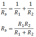
In the case of three resistors connected in parallel:


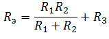
Mixed compound
Mixed compound– a connection, which is a collection of serial and parallel connections. To find the equivalent resistance, you need to “collapse” the circuit by alternately transforming parallel and serial sections of the circuit.

First, let's find the equivalent resistance for the parallel section of the circuit, and then add to it the remaining resistance R 3 . It should be understood that after the conversion, the equivalent resistance R 1 R 2 and resistor R 3 are connected in series.
So, that leaves the most interesting and most complex connection of conductors.
Bridge circuit
The bridge connection diagram is shown in the figure below.

In order to collapse the bridge circuit, one of the bridge triangles is replaced with an equivalent star.

And find the resistances R 1, R 2 and R 3.
Almost everyone who worked as an electrician had to solve the issue of parallel and series connection of circuit elements. Some solve the problems of parallel and series connection of conductors using the “poke” method; for many, a “fireproof” garland is an inexplicable but familiar axiom. However, all these and many other similar questions are easily solved by the method proposed at the very beginning of the 19th century by the German physicist Georg Ohm. The laws discovered by him are still in effect today, and almost everyone can understand them.
Basic electrical quantities of the circuit
In order to find out how a particular connection of conductors will affect the characteristics of the circuit, it is necessary to determine the quantities that characterize any electrical circuit. Here are the main ones:

Mutual dependence of electrical quantities
Now you need to decide, how all of the above quantities depend on one another. The rules of dependence are simple and come down to two basic formulas:
- I=U/R.
- P=I*U.
 Here I is the current in the circuit in amperes, U is the voltage supplied to the circuit in volts, R is the resistance of the circuit in ohms, P is the electrical power of the circuit in watts.
Suppose we have a simple electrical circuit, consisting of a power source with voltage U and a conductor with resistance R (load).
Since the circuit is closed, current I flows through it. What value will it be? Based on the above formula 1, to calculate it we need to know the voltage developed by the power source and the load resistance. If we take, for example, a soldering iron with a coil resistance of 100 Ohms and connect it to a lighting socket with a voltage of 220 V, then the current through the soldering iron will be:
220 / 100 = 2.2 A.
What is the power of this soldering iron? Let's use formula 2:
2.2 * 220 = 484 W.
It turned out to be a good soldering iron, powerful, most likely two-handed. In the same way, by operating with these two formulas and transforming them, you can find out the current through power and voltage, voltage through current and resistance, etc. How much, for example, does a 60 W light bulb in your table lamp consume:
60 / 220 = 0.27 A or 270 mA.
Lamp filament resistance in operating mode:
220 / 0.27 = 815 Ohms.
Circuits with multiple conductors
All the cases discussed above are simple - one source, one load. But in practice there can be several loads, and they are also connected in different ways. There are three types of load connection:
- Parallel.
- Consistent.
- Mixed.
Parallel connection of conductors
The chandelier has 3 lamps, each 60 W. How much does a chandelier consume? That's right, 180 W. Let’s quickly calculate the current through the chandelier:
180 / 220 = 0.818 A.
And then her resistance:
220 / 0.818 = 269 Ohms.
Before this, we calculated the resistance of one lamp (815 Ohms) and the current through it (270 mA). The resistance of the chandelier turned out to be three times lower, and the current was three times higher. Now it’s time to look at the diagram of a three-arm lamp.
All lamps in it are connected in parallel and connected to the network. It turns out that when three lamps are connected in parallel, the total load resistance decreases threefold? In our case, yes, but it is private - all lamps have the same resistance and power. If each of the loads has its own resistance, then simply dividing by the number of loads is not enough to calculate the total value. But there is a way out of the situation - just use this formula: 
1/Rtotal = 1/R1 + 1/R2 + … 1/Rn.
For ease of use, the formula can be easily converted:
Rtot. = (R1*R2*… Rn) / (R1+R2+… Rn).
Here Rtotal. – the total resistance of the circuit when the load is connected in parallel. R1…Rn – resistance of each load.
Why the current increased when you connected three lamps in parallel instead of one is not difficult to understand - after all, it depends on the voltage (it remained unchanged) divided by the resistance (it decreased). Obviously, the power in a parallel connection will increase in proportion to the increase in current.
Serial connection
 Now it’s time to find out how the parameters of the circuit will change if the conductors (in our case, lamps) are connected in series.
Calculating resistance when connecting conductors in series is extremely simple:
Rtot. = R1 + R2.
The same three sixty-watt lamps connected in series will already amount to 2445 Ohms (see calculations above). What are the consequences of increasing circuit resistance? According to formulas 1 and 2, it becomes quite clear that the power and current strength when connecting conductors in series will drop. But why are all the lamps dim now? This is one of the most interesting properties of series connection of conductors, which is very widely used. Let's take a look at a garland of three lamps familiar to us, but connected in series.
The total voltage applied to the entire circuit remained 220 V. But it was divided between each of the lamps in proportion to their resistance! Since we have lamps of the same power and resistance, the voltage is divided equally: U1 = U2 = U3 = U/3. That is, each of the lamps is now supplied with three times less voltage, which is why they glow so dimly. If you take more lamps, their brightness will drop even more. How to calculate the voltage drop across each lamp if they all have different resistances? To do this, the four formulas given above are sufficient. The calculation algorithm will be as follows:
- Measure the resistance of each lamp.
- Calculate the total resistance of the circuit.
- Based on the total voltage and resistance, calculate the current in the circuit.
- Based on the total current and resistance of the lamps, calculate the voltage drop across each of them.
Do you want to consolidate your acquired knowledge?? Solve a simple problem without looking at the answer at the end:
You have at your disposal 15 miniature light bulbs of the same type, designed for a voltage of 13.5 V. Is it possible to use them to make a Christmas tree garland that connects to a regular outlet, and if so, how?
Mixed compound
You, of course, easily figured out the parallel and serial connection of conductors. But what if you have something like this in front of you?
Mixed connection of conductors
How to determine the total resistance of a circuit? To do this, you will need to break the circuit into several sections. The above design is quite simple and there will be two sections - R1 and R2, R3. First, you calculate the total resistance of parallel-connected elements R2, R3 and find Rtot.23. Then calculate the total resistance of the entire circuit, consisting of R1 and Rtot.23 connected in series:
- Rtot.23 = (R2*R3) / (R2+R3).
- Rchains = R1 + Rtot.23.
The problem is solved, everything is very simple. Now the question is somewhat more complicated.
Complex mixed connection of resistances
How to be here? In the same way, you just need to show some imagination. Resistors R2, R4, R5 are connected in series. We calculate their total resistance:
Rtot.245 = R2+R4+R5.
Now we connect R3 in parallel to Rtot.245:
Rtot.2345 = (R3* Rtot.245) / (R3+ Rtot.245).
Rchains = R1+ Rtot.2345+R6.
That's it!
Answer to the problem about the Christmas tree garland
The lamps have an operating voltage of only 13.5 V, and the socket is 220 V, so they must be connected in series.
Since the lamps are of the same type, the network voltage will be divided equally between them and each lamp will have 220 / 15 = 14.6 V. The lamps are designed for a voltage of 13.5 V, so although such a garland will work, it will burn out very quickly. To realize your idea, you will need at least 220 / 13.5 = 17, and preferably 18-19 light bulbs.