The lpt port is for connecting to it. Port connector and Centronics cable
Lpt port, often called parallel, is one of the oldest PC ports. Although these days such a port is not available on all motherboards, it is still somewhat widespread, and therefore many users of computers and office equipment, in particular printers, are very interested in learning about what it is.
First, you need to understand what the abbreviation lpt port means. So, LPT means an abbreviation for a combination of several English words, namely: Line Print Terminal. Translated into Russian, LPT means line printer terminal. Based on the name, it becomes clear that it is primarily intended for a printer. But from a theoretical point of view, some other devices can be connected to LPT. For this purpose, a special adapter is used - an lpt adapter. It should be added that it has another name, accepted among users - printer port.
In general, lpt port has a fairly long history of development. It was developed by employees of the Centronics company, which in the early 70s of the last century specialized in the production of matrix printing devices. In the early 80s this port The printer became widely used by IBM, which used it on its PCs. In that decade, the lpt port even managed to become standard option necessary to connect devices with high speeds available in those years.
Initially, the LPT interface was presented in several different editions. Moreover, in the original version it was unidirectional, i.e. with its help it was possible to transfer information exclusively to a peripheral device. Of course, this kind of situation did not suit many users, because... Already in those years, printing devices were produced that required data transfer in two directions. That is why, some time later, the developers had to improve the LPTl interface several times. This process lasted until its standard was presented, called IEEE 1284. Thus, the developers presented the final port design. New standard had support for several different operating modes. In addition, it was compatible with previous standards. In its final version, the printer interface could support a fairly high information transfer rate for that time, which reached 5 Mb/s!
How does a parallel port work?
The name parallel LPT is due to the fact that data transmission in the cable connected to it is carried out in a parallel manner, for which several conductors are used simultaneously. It is precisely because of this that it differs significantly from som, which is consistent. The number of conductors in the cable that connects to the LPT is usually eight. In addition, it can contain several lines intended for transmitting control signals. Thus, using the com port compared to LPT has a number of strong limitations and disadvantages.
Despite the fact that the Centronics port was mainly used to organize the connection between the printer and the PC, it was nevertheless used for other purposes. For example, using LPT you can directly connect two personal computers to each other - an Interlink cable is usually used for this. As long as the network Ethernet cards did not become widespread, a connection of this type was very popular. Of course, it could not provide users with really high information transfer rates, but despite this, this method of connecting two computers to each other in those years was almost the only possible one. It should be added that there are even special keys electronic type, which are designed specifically for connection to a parallel port.
About the features of LPT operation
As mentioned above, unlike com, LPT supports parallel data transfer. In the first models of personal computers, it was one of the fastest. Its interface, due to the ability to transmit information over several lines, is in many ways similar in its architecture to the buses used in PCs. But it is precisely this kind of circumstance that limits the length of the cable, which cannot exceed 5 meters. Otherwise, there will be constant interference in the connection between the PC and the printer.
To organize normal data transmission, as a rule, 10 signal lines are required. As for the remaining lines, they are used for compatibility with the Centronics cable standard. The maximum voltage setting used on LTP signal lines is typically +5 V.
Port connector and Centronics cable
If we talk about the parallel port connector, it is located on the motherboard itself, although until the mid-90s of the last century this element usually located on the so-called multicard, which was inserted into the expansion slot. The LPT output is a 25-pin DB25 connector.
To establish a connection between a personal computer and printing office equipment using personal port you must use a Centronics cable. In this case, the connector available on office equipment is 36-pin. Thus, the main feature of this cable consists of having two different connectors on both sides.
Also take into account that quite often the Centronics connector is called the cable connector that is intended for the motherboard of a personal computer, but in fact it is a printer connector - i.e. one that includes 36 pins. As for the connector intended directly for LPT, it is called Amphenolstacker. It is necessary to know such differences in names in order to call all things by their proper names.
Bottom line
In conclusion we can say that parallel port Line Print Terminal is a PC interface that is now quite outdated. Despite its wide spread in the last decades of the last century, today this port does not have much support from many companies producing computer equipment, office equipment and software. Despite this, LPT is still successfully used on many models of PCs and printing devices that are outdated today. But quite often, to organize a connection between a computer and an old printer, a com-lpt adapter is required. Today, in principle, they can be found on sale, but if you have the necessary knowledge and skills, you can install such an adapter absolutely independently.
We highly recommend meeting him. There you will find many new friends. In addition, it is the fastest and effective way contact the project administrators. The Antivirus updates section continues to work - always up to date free updates for Dr Web and NOD. Didn't have time to read something? The full contents of the ticker can be found at this link.
Working with an LPT port in Win NT/2000/XP
LPT port (L ine P rin T er) is a parallel interface port that was originally created to connect a printer. The BIOS provides support for the LPT port, which is necessary to organize output via the Centronics interface. The port address space occupies the range &H378-&H37F
The LPT port has 12 output and 5 input lines. Such a fairly large number of lines makes possible connection to the port of simple equipment, which may not even have its own microcontroller. Therefore, this port, despite the disappearance of printers with an LPT interface, is actively used for connecting simple programmers memory chips, JTAG interfaces for flashing (software replacement) satellite receivers, DVD players and other electronic equipment. The LPT port is also popular among modders, since it allows you to connect LCD displays to your computer without making complex interface boards.
Windows 2000/XP does not allow applications to access I/O ports directly. To do this, you need to use a driver running in KERNEL-mode (in operating system kernel mode).
Restricting access to I/O ports for common application programs (running in user mode) makes the operating system more stable. Although, on the other hand, no one is stopping the programmer from writing a driver that accesses the ports.
I wonder what for Intel processor x86, you can write a driver using one of two fundamentally different approaches. The first option is that the driver itself accesses the ports, and the application program only tells the driver what to do. This option is generally standard and preferred.
To solve the problem, there are four popular driver options that allow an application program to access I/O ports: driver DLPortIO, driver UserPort, driver GiveIO.sis, driver Port95nt.
All four options are almost equivalent.
DLPortIO driver
DLportIO - port access driver from the package DriverLINX from Scientific Software Tools, Inc. (http://www.sstnet.com) in an abbreviated form (without description and unnecessary documentation). For normal operation Maintenance programs for LCD indicators can be recommended specifically this driver option.
The driver itself consists of two components:
. DLPortIO.dll - Win32 DLL providing hardware I/O and
. DLPortIO.sys - driver for WinNT, running in OS kernel mode (not required for Win95/98)
In the driver installation package, in addition to these two components, there is also an Install.exe file that moves the two above mentioned ones to the folder Windows drivers and registering them in the system.
There is nothing more to write about this driver. No setup required. Downloaded, installed, use. Don’t forget to look at the end of the article and read about ensuring the functionality of the LPT port.
The installation is simple - run the Install.exe file and install. Once the installation is complete, look in the C:\Windows\System32\drivers folder and check for the presence of two driver files (DLPortIO.sys and DLPortIO.dll). If we see that these files have not been copied, we take them from the installation package and copy them manually. Don't worry, nothing bad will happen to your computer. We reboot the computer and work with the LPT port.
If suddenly, as a result of manipulations with the equipment, you receive a message from the driver like this: “dlportio.sys device driver not loaded. Port I/O will have no effect,” do not panic. This problem is fixed like this:
. Launch regedit.
. We go to the branch in the registry HKEY_LOCAL_MACHINE\SYSTEM\CurrentControlSet\Services\.
. In the dlportio folder, change the value of the parameter Start on 1
.
. Reboot the computer.
UserPort Driver
Driver UserPort opens access to ports in Win NT/2000/XP for programs. This version of the LPT port driver is most often used by “technicians” who work with programmers and JTAGs, since the driver has at least some configuration settings. It can also be used to operate maintenance programs for LCD indicators.
The driver archive contains three files:
. UserPort.sys - driver for WinNT, running in OS kernel mode,
. UserPort.exe is a program for configuring the driver and
. UserPort.pdf - description file.
UserPort installation:
. 1. Unpack the archive into a separate folder.
. 2. Copy the UserPort.sys file to C:\Windows\System32\drivers
UserPort setting:
. Run UserPort.exe.
. A panel with 2 windows will appear in front of us.
The left window refers to the program running in a DOS window, the right one to full screen. By default, they contain LPT port numbers - all of them can be removed using the "Remove" button. You need to enter in both windows required numbers ports that you plan to use.
For use from the driver with most programmers, JTAGs and display service programs, add the following parameters to the left column:
378
, 379
And 37A For LPT1
278
, 279
And 27A For LPT2(If the LPT port address is reassigned in the BIOS).
Let me explain what the numbers mean. 0x378- this is the port address.
. Address 0x378 called basic and is used for writing and reading data to and from the port, via the data bus D0-D7.
. Address 0x379 (basic+1) intended for read bits status from a device connected to the LPT port.
. Address 0x37A (basic+2) serves for bit recording control of the device connected to the LPT port.
Add it like this:
0x378-0x378
0x37A-0x37A

You need to add port addresses to the list through the input window and using the "Add" button. Address 0x379 most often it is not needed and can be omitted, since it is intended for read bits status from a device connected to the LPT port, and most devices (programmers, JTAGs and LCD indicators, especially) do not generate status signals. If desired, you can, on the contrary, enter the entire range of addresses allocated by the system for the LPT port 0x378-0x37F.
Let's go to Control Panel, System, select the Equipment tab, device Manager, go to Ports (COM and LPT) and look at the properties of the LPT port through which you want to establish a connection. In Properties, open the Resources tab and look at the parameter value Input/output (I/O) range. (Usually in Windows XP it is 378 - 37F)
After generating the list of addresses, you need to click the "Start" button, the driver will be launched and the message will appear:

Then click the "Update" button, the driver will be registered in the system, then "Exit". Of course, there is no need to press the "Stop" button while we are using the driver.
If, when you click the "Update" button, the system reboots, you need to try to start driver registration in the system with administrator rights or try to temporarily disable the firewall or antivirus, which may block interference with system processes. If something doesn't work, read UserPort.pdf
To check whether access to the ports has appeared, you can run the program "lpt-test.exe".
After starting the program, a window will appear with the following content:

The absence of the message “LPT port is being tested (Address XXXh)” and the lines following it indicate that the driver is not working.
This program simply sends various numbers to the Dx data register and the Ux control register of the LPT port, and then reads them. The LPT port Sx status register is read only. The number and address of the LPT port being tested is displayed on the screen. If the port is healthy, then no messages should be issued for the Dx and Ux registers.

| LPT-TEST v1.03 1995-2003 Copyright (C) S.B.Alemanov. Moscow "BINAR". During testing, no peripheral devices should be connected to the ports. Dx - reg. data (out), Ux - reg. control (out), Sx - reg. status (inp). LPT1 port is being tested (Address 378h) |
If the Dx or Ux registers are faulty, then the message “no 0” or “no 1” is displayed and the pin number on the LPT connector is indicated (the signals on this pin can be viewed with an oscilloscope). The input of the status register Sx can be either "0" or "1", but usually when LPT port nothing is connected, all inputs of the status register have a "1". The appearance of status “0” at the input of the register may be a sign that the input has been broken, if previously there was always a “1” there.
On some machines, if the data register or control register is faulty, then access to the LPT port does not appear at all. Apparently, when you turn on the computer, the BIOS tests the LPT port and, if it is faulty, disables it.
If problems arise, it is possible that some drivers are interfering with the operation by periodically sending pulses to the LPT port (this can be seen with an oscilloscope). For example, you can disconnect from the LPT port in the printer settings:
turn off LPT1: Printer port
enable FILE: Print to file
After all problems are resolved and the test is passed, access to the ports should appear and you can run a program that uses the LPT port. Otherwise, the device connected to the port on such a machine will not work.
GiveIO.sys driver
Back in 1996, American programmer Dale Roberts conducted a series of experiments, the result of which was the driver GiveIO.sys. Until now, this driver remains one of the popular tools that allows an application program to access I/O ports.
The driver author himself strongly recommends using this driver for debugging purposes only. The final version of the application program should, instead of accessing the I/O ports itself, entrust this task to a driver written specifically for these purposes. The driver must behave "correctly" by checking to see if the device is already in use by some other application.
However, if you are absolutely sure that no one uses the required I/O ports except you (for example, you do not have a printer connected to the LPT), you can safely use the GiveIO.sys driver.
Driver installation:
1. Download the archive, unzip and copy the GiveIO.sys file to the C:\Windows\System32\Drivers directory (assuming that your Windows is installed in the C:\Windows directory).
. 2. Run the install.reg file. The following message will appear on the screen:

. 3. We answer in the affirmative. A message will appear indicating that information was successfully entered into the registry. If you wish, you can verify this. We launch the registry editor regedit.exe and in the branch HKEY_LOCAL_MACHINE\System\CurrentControlSet\Services\giveio We check for the presence of the following entries:

. 4. Reboot the computer and check the operation of programs using the driver.
Driver GiveIO.sys people actively use it, and, over time, appeared other options for installing it.
For example - driver GiveIO.sys if there is a file with "hardware information" GiveIO.inf can be installed through the "Hardware Installation" applet.

We will show the GiveIO.sys driver to the operating system so that it believes in the existence of the "GiveIO" hardware.
Download a set of files for this driver installation option GiveIO.sys(giveio_sys_v2.rar - 78kb). The archive contains the files GiveIO.sys and GiveIO.inf, as well as detailed instructions installation instructions with illustrations.
In addition to the options for “manual” driver installation, several versions of the installer have been written that perform the installation automatically.
Download a set of files for automatic installation drivers GiveIO.sys(giveio_sys_install.rar - 28kb). The archive contains the files GiveIO.sys and instdrv.exe, as well as the file remove-giveio.cmd, with which the driver GiveIO.sys can be removed from the system.
Port95nt driver
The term " driver Port95nt" will not be entirely correct here. Essentially, this is the same driver DLPortIO from the package DriverLINX from Scientific Software Tools, Inc., only in full version, with a couple of port management utilities, with a description and many examples for programmers. There is no benefit to the average user from additional components, and the driver components DLPortIO.sys and DLPortIO.dll are exactly the same as in the shortened version.
I mentioned Port95nt as a driver for two reasons. The first is to complete the list of references to LPT port drivers found on the Internet.
The second reason is that in some cases there may be problems with installing a shortened version of DLPortIO under WinXP. Usually, but not often, this happens in stripped-down "author" builds of WinXP. In this case, you can take the full version of the installer (1.5MB). Although, in my opinion, it will be faster to manually put it in the desired folder DLPortIO.sys and DLPortIO.dll, why bother choosing an installer that can do this for you.
Additional measures
In addition to installing one of the above-mentioned drivers, for normal operation of the LPT port under WinXP OS, you need to edit the registry using a REG file xp_stop_polling.reg(xp_stop_polling.rar - 0.48kb)
Under WinXP, devices using the LPT port are sometimes unstable. The cause of such failures may be the Plug-and-Play (PnP) subsystem in Windows, which periodically polls the LPT to detect connected devices. This polling occurs when the system boots, but it can also occur during operation. Unfortunately, the DLportIO.sys driver and other driver options do not block access to the LPT from other programs when working with the client port of this driver and the PnP subsystem is sure that the port is not busy, accesses it and disrupts the operation of external devices. The REG file is used to fix the problem. xp_stop_polling.reg. This file is written in the registry Windows key, which prohibits such polling while the system is running.
In addition to installing the driver and limiting simultaneous access to the port for programs, to ensure hardware compatibility and normal operation of equipment with the LPT port, it is necessary to set correct address And port operating mode(“Normal”, SPP or EPP, but not ECP).
Configuration via BIOS Setup The following parameters are subject to:
Base address, which can be 378h, 278h and 3BCh. During initialization, the BIOS checks for the presence of ports by address in this order and, accordingly, assigns the logical names LPT1, LPT2, LPT3 to the detected ports. Address 3BCh has a port adapter located on the MDA or HGC board (predecessors modern video cards). Most ports are configured to address 378h by default and can be switched to 278h.
The interrupt request line used, IRQ7 is usually used for LPT1, IRQ5 for LPT2. In many desktop applications, printer interrupts are not used, and this scarce PC resource can be saved. However, when using ECP (Fast Centronics) high-speed modes, interrupt operation can significantly improve performance and reduce processor load.
At the same time, the ECP mode cannot be used with devices that require tight timings (programmers and JTAG interfaces).
In conclusion, a little about terminology:
. SPP(Standard Parallel Port - standard parallel port). Often, to simplify understanding, in the BIOS it is denoted by the term " Normal".
. EPP(Enhanced Parallel Port) - high-speed bidirectional interface option. The purpose of some signals has been changed, the ability to address several logical devices and 8-bit data input, 16-byte hardware FIFO buffer. Maximum speed exchange - up to 2 Mb/s.
. ECP(Enhanced Capability Port) - an intelligent version of EPP. The ability to separate transmitted information into commands and data, support for DMA and compression of transmitted data has been introduced RLE method(Run-Length Encoding - encoding of repeating series).
A modern personal computer would never have gained such enormous popularity if it only performed computing functions. The current PC is multifunctional device, with the help of which the user can not only carry out any calculations, but also perform a lot of different things: print text, control external devices, communicate with other users using computer networks etc. All this huge functionality is achieved using additional devices– peripherals that connect to a personal computer through special connectors called ports.
Personal computer ports
Port- an electronic device running directly on the PC motherboard or on additional boards installed in a personal computer. The ports have a unique connector for connecting external devices – peripherals. They are intended for data exchange between a PC and external devices (printers, modems, digital cameras, etc.). Quite often, in the literature you can find another name for ports - interfaces.
All ports can be divided into two groups:
- External- for connecting external devices (printers, scanners, plotters, video devices, modems, etc.);
- Domestic- for connection internal devices(hard drives, expansion cards).
External ports of a personal computer
- PS/2- port for connecting a keyboard;
- PS/2- port for connecting a mouse;
- Ethernet- connection port local network And network devices(routers, modems, etc.);
- USB- port for connecting external peripheral devices (printers, scanners, smartphones, etc.);
- LPT- parallel port. Serves to connect now outdated models of printers, scanners and plotters;
- COM - serial port RS232. Used to connect devices such as dial-up modems and old printers. Now outdated, practically not used;
- MIDI- port for connecting game consoles, midi keyboards, musical instruments with the same interface. IN lately practically replaced by a USB port;
- Audio In- analog input for linear output sound devices(tape recorders, players, etc.);
- Audio Out- analog output sound signal(headphones, speakers, etc.);
- Microphone- microphone output for connecting a microphone;
- SVGA- port for connecting video display devices: monitors, modern LED, LCD and plasma panels(this type of connector is obsolete);
- VID Out- the port is used to output and input low-frequency video signals;
- DVI- a port for connecting video display devices, more modern than SVGA.
Serial port (COM port)
One of the oldest ports, installed in PCs for more than 20 years. You can find it quite often in literature classic name – RS232. Data exchange using it occurs in serial mode, that is, the transmission and reception lines are one-bit. Thus, information that is transmitted from a computer to a device or vice versa is divided into bits that follow each other sequentially.
The data transfer rate provided by this port is not high, and has a standardized range: 50, 100, 150, 300, 1200, 2400, 4800, 9600, 14400, 38400, 57600, 115200 Kbps.
A serial port was used to connect such “slow” devices to a PC as the first printers and plotters, dial-up modems, mice, and even to communicate between computers. No matter how slow its speed, in order to connect the devices to each other, only three wires were required - the data exchange protocol was so simple. It is clear that for full-fledged work it was necessary more conductors in the cord.
Today, the serial port is practically no longer used and is completely supplanted by its younger, but also faster “brother” - USB port. It should be noted, however, that some manufacturers still equip their motherboards with a COM port. However, the name itself - “serial port” is still used by software developers. For example, Bluetooth devices and cell phone ports are often presented as a “serial port.” This may be a little confusing, but this is done because they also transfer data serially, but at a higher speed.
If for some reason you may need a COM port, but your PC does not have one, then for this purpose you can use an adapter that connects to a modern USB port, available on all modern PCs, and on the other hand, such an adapter has serial port connector. There is, however, one limitation: if the software accessed directly the hardware of a real COM port, then it will not work with such an adapter. In this case, you need to purchase special fee, which is installed inside your PC.
Structurally, the PC serial port has a male connector (with protruding pins):


Today, the 25-pin serial port connector has practically fallen out of use and has not been installed on a PC for several years. If the manufacturer provides the motherboard with a COM port, then it is a 9-pin DB9 connector.
It is an interface for connecting devices such as printers, scanners and plotters.

Allows you to simultaneously transmit 8 bits of data, albeit in one direction - from the computer to the periphery. In addition to this, it has 4 control bits (as with data bits, control bits are transferred from the PC to the external device), and 4 status bits (these bits can be “read” by the computer from the device).
IN recent years, The LPT port was improved, and it became two-way, that is, it became possible to transmit data bits through it in both directions. Today it is outdated and practically not used, although motherboard manufacturers still include it in its composition.
Enthusiasts and radio amateurs often use this port to control any non-standard devices (crafts, etc.).
USB interface
USB– this is an abbreviation of the full name of the port – universal serial bus (“universal serial bus”).

It is one of the most widely used ports on a personal computer today. And this is no coincidence - he technical specifications and ease of use are truly impressive.
The data exchange speed for the USB 2.0 interface can reach 480 Mbit/s, and for the USB3.0 interface – up to 5 Gbit/s (!).
Moreover, all versions of this interface are compatible with each other. That is, a device using interface 2.0 can be connected to a USB3.0 port (in this case, the port will automatically reduce the speed to the desired value). Accordingly, a device using a USB 3.0 port can be connected to a USB 2.0 port. The only condition is if normal operation requires a speed higher than the maximum USB speed 2.0, then normal operation of the peripheral device will not be possible in this case.
In addition, the popularity of this port is also due to the fact that the developers included one very useful feature in it - this port can serve as a power source, for an external device connected to it. In this case it is not required additional block to connect to electrical network, which is very convenient.
For version USB port 2.0, the maximum current consumption can reach 0.5A, and in the USB3.0 version – 0.9A. It is not recommended to exceed the specified values, as this will lead to failure of the interface.

Developers of modern digital devices, always strive to minimize. Therefore, structurally, this port can have, in addition to a standard connector, also a mini-version for miniature devices - mini-USB. None fundamental differences from a standard USB port except the design itself mini-USB connector does not have.

Almost everything modern devices have a USB port for connecting to a PC. Ease of installation - the connected device is recognized by the operating system almost immediately after connection, making it possible to use such a port without special “computer” knowledge. Printers, scanners, digital cameras, smartphones and tablets, external drives - this is just a small list of peripheral equipment that currently uses this interface. A simple principle - “plug and play” made this port truly a bestseller among all currently available personal computer interfaces.
Fire-Wire port (Other names - IEEE1394, i-Link)
This type of interface appeared relatively recently - since 1995. It is a high-speed serial bus. Data transfer rates can reach up to 400 Mbit/s in the IEEE 1394 and IEEE 1394a standard, 800 Mbit/s and 1600 Mbit/s in the IEEE1394b standard.
This interface was originally designed as a port for connecting internal drives (SATA type), but licensing policy Apple- one of the developers of this standard, demanded payment for each controller chip. Therefore, today only a small number of digital devices (some models of cameras and video cameras) are equipped with this type of interface. This type of port never became widespread.


The importance of this interface can hardly be overestimated; as a rule, it is what is used to connect a personal computer to a local network or to access the Internet in most cases. Almost all modern PCs, laptops and netbooks are equipped with an Ethernet port built into the motherboard. This is easy to verify if you inspect the external connectors.

To connect external devices, a special one is used, which has identical connectors at both ends. connectors – RJ-45, containing eight contacts.

The cable is symmetrical, therefore, the order in which the devices are connected does not matter - any device of your choice can be connected to any of the identical cable connectors - a PC, router, modem, etc. It is marked with the abbreviation - UTP, common name - " twisted pair» . In most cases, for both home and office use, a cable of the fifth category, UTP-5 or UTP-5E, is used.

The speed of data transmitted over an Ethernet connection depends on the technical capabilities of the port and is 10 Mbit/s, 100 Mbit/s and 1000 Mbit/s. It should be understood that this throughput is theoretical, and that in real networks it is somewhat lower due to the peculiarities of the Ethernet data transfer protocol.
Also, you should keep in mind that not all manufacturers install high-speed chips in their Ethernet controllers, since they are very expensive. This leads to the fact that, in practice, real speed data transmission is significantly lower than indicated on the packaging or in the specification. As a rule, almost all Ethernet cards are compatible with each other and from top to bottom. That is, newer models that have the ability to connect at speeds of 1000 Mbit/s (1 Gbit/s) will work without problems with older models at speeds of 10 and 100 Mbit/s.
To visually monitor the integrity of the connection, the Ethernet port has Link and Act indicators. Link indicator - lit green when correct and working physical connection, i.e. the cable between the devices is connected, it is intact, the ports are working. The second Act indicator (“activity”) is usually orange and flashes while transmitting or receiving data.
Internal ports of a personal computer
As mentioned above, internal ports designed for connecting peripherals such as hard drives, CDs and DVD-ROMs, card readers, additional COM And USB ports etc. Internal ports are located either on the motherboard or on additional expansion cards installed in the system bus.
A now outdated interface for connecting older models of hard drives (“hard drives”, HDD). After the creation of the SATA interface, it was called the PATA interface, or ATA for short. PATA – ParallelAdvanced Technology Attachment. This parallel data transfer interface for connecting drives was developed in mid-1986 by the now famous company WesternDigital.

Depending on the manufacturer, the motherboard may contain from one to four IDE channels. Modern manufacturers, as a rule, leave only one IDE port for compatibility, and recently it has also been excluded from the list motherboard, being completely supplanted modern interface SATA.
The data transfer speed in the latest version of the EnhancedIDE interface can reach 150 Mbit/s. Devices are connected using an IDE cable having 40 or 80 cores for the old or new interface type, respectively.


Typically, you can connect up to two devices simultaneously to one IDE port using a single cable. In this case, using jumpers on the drives that determine the “seniority” of devices operating in pairs, the operating mode is selected - on one device - "master", and for the other "subordinate" (slave).
You can connect either the same type of device, for example, two hard drives or two DVD-ROMs, or different devices in any combination - DVD-ROM and HDD or CD-ROM and DVD-ROM. The connector for connection does not matter, you should just pay attention that the two connectors for connecting peripherals are shifted for convenience to one of the ends of the cable.
You should also keep in mind that by connecting a “fast” device designed for an 80-wire cable using an old 40-wire cable, you will greatly reduce the exchange speed. In addition, if one of the devices in the pair has an old (slow) ATA interface, then the data transfer speed in this case will be determined precisely by the speed of this device.
If there are two IDE ports and two drives inside the PC, to increase the data transfer speed you need to connect each drive to separate port IDE.
This interface is a development of its predecessor IDE interface, with the only difference that, unlike his “senior comrade”, he is not parallel, but serial interface. SATA – SerialATA.
Structurally, it has only seven conductors for its operation and a much smaller area of both the connector itself and the connecting cable.

The data transfer speed of this interface is significantly higher than the outdated IDE and, depending on the SATA version, is:
- SATARev. 1.0 – up to 1.5 Gbit/s;
- SATARev. 2.0 – up to 3 Gbit/s;
- SATARev. 3.0 – up to 6 Gbit/sec.
Just like the IDE interface, the cord for connecting devices is “universal” - the connectors are the same on both sides, but unlike its “brother”, now using one SATA cable you can connect only one device to one SATA port.

But there is hardly any need to be upset about this. Manufacturers have made sure that the number of ports is sufficient for the most different applications, installing up to 8 SATA ports on one motherboard. The third revision SATA port connector is usually bright red.
Additional ports
Most motherboards are equipped by manufacturers with an additional number of USB ports, and sometimes with another, additional COM port.

This is done for the convenience of the user. Most modern desktop PC cases have USB connectors installed on the front panel for convenient connection external drives. In this case, you do not need to reach for the back wall system unit and “get” into the USB connector, which is connected to back panel.
This connector is on the front panel and connects to an additional USB port installed on the motherboard. Among other things, displayed on the rear panel USB interfaces there may simply not be enough, in mind large quantity peripheral devices, in this case you can purchase additional bar With USB connectors and connect them to additional ports.

All of the above also applies to other ports installed on the motherboard. For example, sequential COM port or FireWireIEEE1394 may simply not be displayed on the back panel of a personal computer, but at the same time it is present on the motherboard. In this case, it is enough to buy the appropriate cable and take it out.
It would be technically incorrect to call these connectors ports, although the method of connecting additional cards to them is still somewhat similar to other conventional ports. The principle is the same - plug it in and turn it on. In most cases, the system will find the device itself and request (or install automatically) drivers for it.

In such buses, for example, an external graphics card is installed, sound card, internal modem, video capture card, others additional fees extensions that allow the PC to expand its functions and capabilities.
PCI and PCIe buses are incompatible with each other, so before purchasing an expansion card, you need to find out which system buses are installed on the motherboard of your PC.
PCIex 1 and PCIex 16 are modern implementations of the older PCI buses developed in 1991. But unlike its predecessor, it is serial bus, and besides this, all PCIe buses are connected in a star topology, while the old PCI bus was connected in parallel to each other. In addition, the new tire has the following advantages:
- Possibility of hot replacement of boards;
- The bandwidth has guaranteed parameters;
- Control of data integrity during reception and transmission;
- Controlled energy consumption.
Tires vary PCI Express the number of conductors connected to the slot, through which data is exchanged with the installed device (PCIex 1, PCIex2, PCIex 4, PCIex 8, PCIex 16, PCIex 32). The maximum data transfer speed can reach 16 Gbit/s.
Download the printer port pinout:
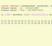
IEEE 1284 (printer port, parallel port, English Line Print Terminal, LPT) - international parallel interface standard
At the core this standard lies the Centronics interface and its extended versions (ECP, EPP).
The name "LPT" is derived from the name standard device printer “LPT1” (Line Printer Terminal or Line PrinTer) in operating systems of the MS-DOS family. Centronics interface and IEEE 1284 standard
Centronics parallel port - port used since 1981 in personal computers from IBM for connecting printing devices, developed by Centronics Data Computer Corporation; has long become a de facto standard, although in reality it is not officially standardized at the moment.
This port was originally designed for simplex (unidirectional) data transfer only, since the Centronics port was intended to be used only for printer operation. Subsequently, different companies developed duplex interface extensions (byte mode, EPP, ECP). The international standard IEEE 1284 was then adopted, describing both the basic Centronics interface and all its extensions.
Types of Parallel Port Connectors
Centronics 36-pin cable connector for external device connection (IEEE 1284-B)
25-pin DB-25 connector used as an LPT port on personal computers (IEEE 1284-A)
The port on the control device (computer) side has a 25-pin 2-row DB-25-female connector (IEEE 1284-A). Not to be confused with a similar male connector (“male”), which was installed on older computers and is a 25-pin COM port.
Peripherals typically use a 36-pin micro ribbon Centronics (IEEE 1284-B) connector, so parallel cables for connecting peripherals to a computer are typically made with a 25-pin DB-25-male connector on one side and a 36-pin IEEE 1284-B to another (AB cable). Occasionally, an AC cable with a 36-pin MiniCentronics connector (IEEE 1284-C) is used.
There are also CC cables with MiniCentronics connectors on both ends for connecting devices using the IEEE 1284-II standard, which is rarely used.
The length of the connecting cable should not exceed 3 meters. Cable design: twisted pairs in a common shield, or twisted pairs in individual shields. Ribbon cables are rarely used.
To connect a scanner and some other devices, a cable is used that has a DB-25-male connector installed instead of a connector (IEEE 1284-B). Typically, the scanner is equipped with a second interface with a DB-25-female (IEEE 1284-A) connector for connecting a printer (since a computer is usually equipped with only one IEEE 1284 interface).
The scanner circuitry is designed in such a way that when working with a printer, the scanner transparently transfers data from one interface to another. Physical interface
Connector interface
The basic Centronics interface is a unidirectional parallel interface and contains signal lines characteristic of such an interface (8 for data transmission, strobe, device status lines).
Data is transferred in one direction: from the computer to an external device. But it cannot be called completely unidirectional. Thus, 4 return lines are used to monitor the status of the device. Centronics allows you to connect one device, so to use multiple devices together, you need to additionally use a selector.
Data transfer speed can vary and reach 1.2 Mbit/s.
Standard Centronics IEEE 1284 Printer lpt cable wire cords:
Simplified table - Centronics LPT interface signal diagram - connector
| Contacts DB-25 IEEE 1284-A |
Contacts Centronics IEEE 1284-B |
Designation | Note | Function |
|---|---|---|---|---|
| 1 | 1 | Strobe | Transfer cycle marker (output) | Computer Management |
| 2 | 2 | Data Bit 1 | Signal 1 (output) | Data Computer |
| 3 | 3 | Data Bit 2 | Signal 2 (output) | Data Computer |
| 4 | 4 | Data Bit 3 | Signal 3 (output) | Data Computer |
| 5 | 5 | Data Bit 4 | Signal 4 (output) | Data Computer |
| 6 | 6 | Data Bit 5 | Signal 5 (output) | Data Computer |
| 7 | 7 | Data Bit 6 | Signal 6 (output) | Data Computer |
| 8 | 8 | Data Bit 7 | Signal 7 (output) | Data Computer |
| 9 | 9 | Data Bit 8 | Signal 8 (output) | Data Computer |
| 10 | 10 | Acknowledgment | Willingness to accept (input) | Printer Status |
| 11 | 11 | Busy | Busy (entrance) | Printer Status |
| 12 | 12 | Paper End | No paper (input) | Printer Status |
| 13 | 13 | Select | Select (input) | Printer Status |
| 14 | 14 | Auto Line Feed | Autofeed (output) | Computer Management |
| 15 | 32 | Error | Error (input) | Printer Status |
| 16 | 31 | Init | Initialize (exit) Initialize Printer (prime-low) | Computer Management |
| 17 | 36 | Select In | Print Control (Output) Select Input | Computer Management |
| 18-25 | 16-17, 19-30 | GND | General | Earth |
The wiring of the Centronics IEEE 1284 Printer Cable lpt - com9 port can also be shown in the form of a picture image
LPT port is the place on the computer where the printer is connected. But you can put a lot more interesting things in there. Including the schemes you come up with. For example, through the LPT port, the lights in the room were turned on, the lock on the door was opened and the radio was turned off.
This is what the connector looks like on a computer.
It has 25 pins:
| N | Direction | Signal |
|---|---|---|
| 1 | Exit | Data Strobe |
| 2 | Exit | Data 0 |
| 3 | Exit | Data 1 |
| 4 | Exit | Data 2 |
| 5 | Exit | Data 3 |
| 6 | Exit | Data 4 |
| 7 | Exit | Data 5 |
| 8 | Exit | Data 6 |
| 9 | Exit | Data 7 |
| 10 | Entrance | Acknowledgment |
| 11 | Entrance | Busy |
| 12 | Entrance | Paper Out |
| 13 | Entrance | Select |
| 14 | Exit | Auto feed |
| 15 | Entrance | Error |
| 16 | Exit | Init |
| 17 | Exit | Select Input |
| 18-25 | Ground |
For simple circuits control we need conclusions:
2 - 9
- these are outputs Data0-7.
18 - 25
- this is earth (minus). Usually (not always) they are connected to the computer case.
This is the basic set of pins needed to make your own circuits.
I would also like to draw your attention to the conclusion 1 - this is "Data Strobe". As I understand it, a positive signal at this output tells the device that it needs to read the next command. If we do not power this output programmatically, the printer will simply not pay attention to the other outputs.
Pins are used to enter information into the port 10-13, 15 . More details later.
Port outputs can only accept 2 states - log0 And log1. When you turn on the computer, the output states change quickly, then go to log0. Depending on the type of motherboard, one or two outputs may go to log1. Next, when loading the OS Windows states vhldov may change again. After loading is completed, the system does not touch the outputs until printing or “search for equipment” begins.
Source: zps-electronics.com
| This diagram is also often viewed: |