Wi-fi antenna: a master class on the manufacture and design of powerful home-made devices. Homemade Wi-Fi Antenna
We touched upon the designs of a directional Wi-Fi antenna earlier. Bisquare, canned homemade rarities. People with enviable constancy are looking for a chance to get a better design. It was mentioned: instead of a traditional wire, it is better to take a PV1 wire of a similar section, which protects the installed antenna from bad weather. A board with double-sided foil, which is often recommended to be used as a reflector, does not tolerate bad weather very well, is not protected by anything, it is problematic to supply the design with a special case. The wind load on the product will increase. Today's review is devoted to methods for improving the design. Do-it-yourself Wi-Fi antenna for any bad weather!
Important! Try using shrink wrap for protection. Put on a reflector "fur coat", blow with a hairdryer. Soon the textolite will be tightly covered with a polymer film.
Bi-square Wi-Fi Antennas
The Wi-Fi antenna, built according to the biquad scheme, is formed by a grounded reflector, a figure-eight emitter with right (90 degrees) angles. It turns out something resembling trendy glasses with a thin bridge in the middle. The lower half is planted on the ground, the upper half - on the signal core of the cable RK - 50.
True, the antenna for Wi-Fi will be smaller in size. The side of the square along the midline of the copper core of the emitter is 30.5 mm. So, the figure eight is 1.5 (half the length of the side of the square) cm from the reflector and is parallel to the plate. In our case, the getinax fee is bad because it is difficult to get. A reflector is simply a sheet of electrically conductive metal. Tin, steel, aluminum will fit. Given the size of the emitter, you can make a WiFi antenna reflector using a 5.25 inch laser CD.
Biquadrat Kharchenko
The internal reflective aluminum layer is designed so that the laser beam does not lose energy on the surface. In addition, there is a hole in the center for the N-connector. It remains to open the protective plastic shell, put the reflective layer on the screen of the PK-50 cable. Please note: if the N-connector is not 1.5 cm away from the reflector with the emitter, the reception conditions will worsen. It is necessary to achieve the indicated position by placing thin metal washers or in place.
We remind you: the bi-square figure eight bends from the middle by turning 90 degrees. Both ends of the PV1 1x2.5 cable will return to the point. The thickness of the wire is 1.6 mm in diameter, between the centers of the core, the side of the square is 30.5 mm. The ends sit on the connector screen, are combined with a reflector (CD), the middle part will serve as a signal pickup. The radiation pattern of the device is sharply narrowed, equipped with one main lobe, which we direct to the signal source. If the case is in a room, you will have to experimentally find a reflected beam located in almost any direction.
The reflector will protect against neighborly interference, increase power. Blocks the multipath effect, which is of little use to the equipment. A homemade Wi-Fi antenna only accepts from a narrow sector. Thanks to this, we will connect the houses opposite by a network, which would not be possible with the supplied access point.
Please note: in other cases, there may not be an input connector on the case for connecting an antenna. Such access points are equipped with built-in metal circuits that receive radio waves. Traditionally, they look like intricate flat figures on the inside of the case. We'll have to unsolder the built-in antenna.
A capacitor can stand nearby, the capacitance serves the purpose of compensating for the compression ratio of the circuit. The built-in antenna is small, powerless to form a full-fledged device for receiving radio waves. The defect is neutralized by a tuning capacitor.
The element is not needed, because a full-sized antenna for a Wi-Fi router does not need to be compensated. Tear the homemade switching circuits above the capacitor. Do not use a typical 100W soldering iron when doing the installation. It will burn the electronic components of the board. You will need a small soldering iron equipped with a 25W needle tip.
The weight of the CD is small, the wind load is low, in contrast to the bulky design and will not kill anyone from below with a falling getinax board. It is recommended to avoid placing products in the sun, but in our case, the recorded information does not play a great role. If desired, seal the N-connector, extending the life of the solder joint. A special gel compound is used for mounting printed circuit boards. Similar ones are produced by the Allur company (St. Petersburg). A few words will explain how to make a Wi-Fi antenna more powerful with your own hands.
Bisquare antennas
Prologue: 2 weeks, I couldn’t find the reason for it, then I turned the antennas into a vertical one and got 20 Mbit per 5 km, instead of horizontal 4.
Vampirenysh, member of the forum Local Networks of Ukraine (spelling copied).
Before you buy a Wi-Fi antenna, think about it: theory shows that emitters arranged in rows narrow the radiation pattern in the direction perpendicular to the line along which to line up the elements. Translated into Russian, it means: if our houses are separated by 100 meters, the width of the antenna viewing sector for implementing the Wi-Fi communication channel barely exceeds 15 degrees. Useful power will be directed to the window of a friend (it will only harm the inhabitants of the apartment!). To implement the circuit, use a dual biquad antenna. You can increase the speed if you give the same to a friend on DR!
How to make a Wi-Fi antenna so that it does not interfere with neighbors. You can protect yourself from uninvited guests by changing the channel, polarization. There are three ways to protect the channel with the antenna configuration:
- Frequency selection.
- Direction selection (beam narrowing).
- Choice of polarization.
Usually, when there is Wi-Fi provided by the provider, the values \u200b\u200bare set by the communication provider, the client has to obey, but if you have your own equipment, the situation is different. We can put the antenna on vertical polarization if the neighbors use horizontal polarization. Our equipment will stop seeing each other. Can be done unilaterally or negotiated. Antennas will be needed like a biquad, set aside.
Television operates on horizontal polarization, communications on vertical polarization. Just a tradition, it is convenient to keep the walkie-talkie pin perpendicular to the ground when you speak. In this context, it is beneficial to use vertical polarization, usually found in routers. We offer a simple rule:
- Position with a friend opposite the antenna on the windows in the same way. Spatial compatibility is provided, which is a subspecies of electromagnetic. Microwaves, telephones, a mountain of 2.4 GHz interference equipment have been released. Position the antennas equally, vertically, horizontally, tilted. Experimentally look for the position at which the speed is greatest.
The promised novelty: a design of four squares lined up in a row. The radiation pattern will become narrow in the direction perpendicular to the formation. Copper wire or solid wire with a cross section of 2.5 mm 2 50 cm long. We recommend taking it with a margin. If a standard biquad Wi-Fi antenna for a laptop is an in-phase array of two frames, in our case there are four frames.

Frame for dual biquad antenna
When the wave moves, the current in neighboring squares is directed oppositely along the contour. Due to this, the effect of the impact of the field is added up. Now we need to get four in-phase squares. Find the middle of the wire, make a 90 degree bend. We measure 30 mm, make bends on each side in the opposite direction. We retreat twice as much, again bend in the first direction. You get a large letter W. Another 30 mm - bend the edges down at 90 degrees. One half is ready.
We do the second in the image and likeness so that the ends return to the point of the initial bend. Please note that it is not in vain that we recommend using a wire with a PVC sheath - the two crosshairs in the figure are mutually isolated.
We cut off the excess wire so that the ends do not reach the first bend by two or three millimeters. A Wi-Fi antenna for a computer requires a reflector, a good piece of foil textolite or a standard flat sheet will do. We use the N-connector for the connection.
The emitter is separated from the reflector by 1.5 cm in area. We plant the ends on the ground, the middle - on the signal core (cable for Wi-Fi antenna RK - 50). To reinforce the edges of the figure, use a ceramic or plastic tube. For fixing, electrical insulation, use glue, sealant. The street version is recommended to find a plastic case. Take a smaller distance between the homemade antenna and the receiver.
The next meeting will discuss Wi-Fi radio.
Manufacturing.
First of all, you need to make a reflector - this is a metal sheet 450x350 mm (the back of the antenna). It serves to reflect and transmit wifi waves to vibrators and, in combination, serves as the body of the antenna itself.
To do this, take a fairly thick sheet of iron. For example, a case from an old washing machine or a baking tray will do the job. We cut out the desired size with a grinder and clean it from rust. see photo 1 on the right
Let's postpone while aside the blank of the reflector and we will be engaged in the manufacture of vibrators, which will be located on a one-sided fiberglass 1.5 mm. To do this, you need to purchase a vinyl stencil of vibrators with a mounting film on a self-adhesive basis. Such things are done in plotter cutting workshops according to the provided drawing.
Download drawing Delta Ds 2400-21. Copy to usb flash drive. At the cutting plotter company, explain to the manager what the actual dimensions of the drawing details should be!
Before sticking the stencil, remove small scratches and polish the copper surface of the fiberglass with the help of zero and GOI paste. Degrease with a solvent (acetone), the surface! Carefully transfer the stencil onto the copper surface of the fiberglass. Let's start etching the antenna circuit board.
Pour hot water in a suitable size container, add copper sulfate and edible salt in a ratio of 1: 3, mix well and lower the fiberglass down with copper. So that the board does not sink, first stick the foam on the opposite side using double-sided tape. Wait for the complete dissolution of excess copper. see photo 2 on the left.
When the process is over, rinse the fiberglass with clean water, remove the vinyl from the vibrators and tracks. Make a hole for the N-235 TGT connector pin and tin. To protect against the external environment and against oxidation, cover the side of the antenna with vibrators - insulating varnish!
Attach fiberglass to the reflector, make a mark and drill a hole for the n-type connector. Same way make holes for outdoor wifi antenna mount kit, see photo 3 on the right.
Next, we need to connect the reflector and the fiberglass board together. The gap between the reflector and the vibrators must be 9mm.!
Here's how we do it - glue the pieces of 6 mm floor laminate to the reflector with a THIN layer of glue. Before that, evenly place them on the fiberglass using double-sided tape, see photo 4 on the left.
Laminate 6 mm + fiberglass 1.5 mm + glue 1.5 mm = gap 9 mm.
Now we put it in its place and tighten the N-235 TGT connector tightly. After the glue dries, we unstick (holding on double-sided tape) fiberglass from the reflector. We close the laminate and the connector with masking tape, and paint the reflector on both sides with paint for metal for outdoor use. The reflector is almost ready, we attach the design of the external antenna mount.
Next, we apply a thin layer of glue "moment" on the laminate and connect the reflector with fiberglass. Having inserted the contact of the n-type connector into the hole, we solder its tip to the copper track of the vibrators. See photo 5 on the right.
In this example, a protective cover for the antenna is not provided. Instead, Soudal Fix All Crystal hybrid adhesive-sealant is used and applied along the perimeter between the reflector and fiberglass, See photo 6 on the left. Then the front part of the wi-fi antenna is covered with three layers of white acrylic paint. Check the paint first to see if it will shield your antenna. Paint a piece of construction paper and when the paint is completely dry, close the front side of the wi-fi antenna. If the signal does not change, feel free to use this paint. See photo 7 on the right.
Let's check this product in action.
Here are the results of testing a DIY Wi-Fi antenna:
In order to connect the antenna, we need an external USB wifi adapter. This example uses "alfa awus036h 1000mw - Taiwan".
First, connect the adapter, without an antenna, and see what it will show us, and will it even work? As it turned out, alfa found three points. We will focus on the connected point -66 dBm. For half an hour, the signal remained almost unchanged, and this was without any antenna. See photo 8 on the left.
Now, without changing the location, let's check our homemade Wi-Fi antenna by pointing it towards the router. As you can see, the result is very different for the better. See photo 9 on the right. The connected point signal improved from -66 dBm to -45 dBm. There are three more spots.
66-45=21.
It turns out that the antenna gain is 21 dB.
Homemade external omnidirectional Wi-Fi antenna
So, we need an external antenna for the 802.11b access point, to which the directional antennas of all other users of the wireless network (WLAN) will be oriented. This antenna will have to receive and transmit signals in all directions, so that the network can be accessed from any direction, i.e. must have a circular pattern. In other words, we need external omnidirectional WiFi antenna.
Of course, there are factory solutions for this, but they cost a lot of money, for example, this antenna ANT24-1500 costs 175 USD (Fig. 1)
and this ANT24-0500- 65 USD (Fig. 2)

Rice. 2
And in general they fool our brother and not only in this area, the cost of these products is a penny! Therefore, we will make the antenna ourselves and it will work no worse than the factory ones, since the laws of radio engineering are the same for everyone, and here everything will rest only on accuracy and workmanship.
Our WiFi antenna will be a classic whip antenna with a circular radiation pattern in the horizontal plane, called the Ground Plane by radio amateurs, converted to the 2.440 MHz band we need. The antenna is a quarter-wavelength pin with counterweights of the same length, located at 135° relative to the pin.

Why exactly 135°? Because only with these parameters our antenna will have a wave impedance of 50 ohms and will be matched with the 50 ohm cable that feeds it. Here is how the wave impedance changes as this angle changes.

When the antenna mismatches with the cable, not all the energy suitable for the antenna will be radiated by it, i.e. here it will be necessary to observe the manufacturing accuracy. The length of the pin, for the middle of our 2.440 MHz band, will be 27.95 mm (28 mm rounded), the length of the counterweights will be 30.72 mm (31 mm rounded).

Why is the pin shorter than counterweights? Here we observe such a radio engineering rule as a shortening factor, since the length of the radio wave in different media is different. For our antenna with a pin diameter of 2.28 mm, it will be equal to 0.91. It is desirable to maintain the dimensions of the pin and counterweights as accurately as possible, the wave impedance of the antenna also depends on this. It is necessary to try to the flesh to fractions of a millimeter, since at these frequencies the antenna is very small and even a couple of millimeters of discrepancy in size greatly violates the conformity of the length of the quarter-wave pin. It is desirable to make the number of counterweights at least 12, and it is even better to cut a cone from copper foil.
Practical implementation
An omnidirectional WiFi antenna is made by releasing the central core of the power cable from the braid, taking into account the required length of the pin.

The counterweights are made of a braid of the same cable twisted and laid to the desired angle. We cut off the upper cover of the cable at a level of 31 mm, remove the braid and shorten the pin to 28 mm. We tin the tip of the pin with a soldering iron so that the wiring of the central core does not disperse and remove the insulation from the central core, since if you leave it, you will need to recalculate the shortening factor, taking into account its influence. All this must be hermetically sealed in a plastic box so that even fresh air does not penetrate.

And here is how the craftsmen behind the hillock do it:

Rice. 8 

Firstly, only about 2 dB is lost here, but we simply don’t have it, secondly, the shortening factor is not taken into account, thirdly, the shape of the connector itself distorts the shape of a theoretically correct antenna of this type.
Cable selection.
Since the RF output of all access points usually has an impedance of 50 ohms, we don’t have much choice - the cable must be a characteristic impedance of 50 ohms. Well, of course, a Belden-type H-1000 cable with an attenuation of 0.22 dB / meter would be ideal for us, but we don’t have that kind of money. Therefore, you can choose a cheaper and more affordable RK-50-7-11 with attenuation at our frequencies of about 0.6 dB. Naturally, it should be without joints and damage, preferably new.
We connect the cable to the access point cheaply and cheerfully.
Usually all connections in this case are made using special connectors.


Rice. 12
But we don't use it for known reasons. Instead, we take pliers and, without a drop of regret, break the regular indoor WiFi antenna from the access point about 2 centimeters from the bending knee of the antenna.

Be careful, there is a thin cable inside, we will still need it. You pull it out along with a real antenna located inside this case.

Here she is. By the way, it is described in Fig. 4, only to reduce its resistance to 50 ohms, they shortened it to 26 mm, thus making it less effective than a quarter wave antenna.

We unsolder the cable at the base of the antenna pin, pull it out of the tube and cut it in this place. Then we release about a centimeter of the central core from the braid, fluffing it up and bending it back. Next, we release about 4 mm of the central core from the insulation and tin this end with a soldering iron. Now we take a large cable, cut off about a centimeter of the outer sheath, pull back the braid and give the inner insulation the appearance of a cone. Then, with a needle, we try to make a hole between the wires of the core with a depth of 4 mm, preferably closer to the center of the core.

We will stick a core of a small cable into this hole.

And then with a small drop of tin with rosin we solder both cores. We fill the place of soldering with molten insulation material of the central core from some unnecessary piece of the same cable. Next, we connect the braids of both cables on all sides evenly and solder so that there are no gaps, you can add more copper hairs and tin for this or use copper foil. Then we wrap it all with electrical tape and get this.

For all the clumsiness and sloppiness of the product that I made, everything works at a distance of 90 m with a signal level of 61% at a full speed of 11 Mbps.

Considering that the length of my cable is about 8 meters and a friend at the other end of the 12 meters has the same cable with the same connections, feeding a simple canned antenna that has not been brought to mind (for those who are interested, here is an article on a canned Wi-Fi antenna), then I think it's pretty good.
After a year, I bought a smart nokia n95 with wi-fi support and was able to take new measurements.
So, the access point is the same with a power of 15dBm, i.e. 31.6 milliwatts, the nokia n95 wi-fi module has a power of 100 milliwatts, but this is not important, since the communication range will be determined by the lowest power device in the system, i.e. at that distance where the TD hears the Nokia, the Nokia will no longer hear the TD due to its lower power. WiFi antennas in both cases are omnidirectional: on the AP everything is the same as described above, and on Nokia it has a built-in antenna. According to the gps readings, I determined the distances with an accuracy of a couple of meters. Having moved to a distance of 1100 meters, the connection was still stable. From the HTTP server, everything swayed without disruption, Internet access went fine, although the speed was already at a minimum of 1 megabit sec. At a distance of 1200 meters, the connection was already very eager to work, it was impossible. When using more powerful APs such as the DWL-2100AP, it will be possible to communicate over a longer distance.
There was a direct line of sight and without any directional antennas. Although I have a suspicion that in Nokia the antenna has some directivity, although not pronounced - it catches a little better in a vertical position with the left side to the signal source. Of course, the connection will not be good in any place where the phone is turned on, usually on hillocks, the connection may be better in the lowlands.
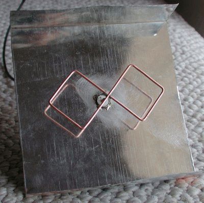
Now in amateur radio practice, antennas for amplifying 3G, 4G, Wi-Fi signals of the "Bikvadrat" type are very common.
Such an antenna has a directional action, which may not always be an advantage, but even a disadvantage. An example is this: you need to amplify the signal of your router so that you can catch it in any part of your house. If you use a directional antenna, then the signal will most likely be well available only in the field of action of this antenna. Surely this will be only one room where she will be directed. It is good to use such an antenna only for long-distance communication, provided that you know where to point it.
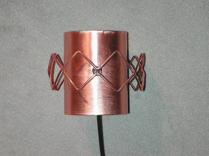
To amplify your WI-FI signal in all directions, an antenna is suitable, which I will show you. It is close to the whip antenna in its directivity characteristics, with the exception of greater sensitivity.
By structure, this is actually the same bi-square, only twice directed in opposite directions. Plus, this antenna is many times simpler than the classic biquad, since it has neither a rack nor a reflector.

How to calculate the antenna?
Just please don't be scared, fifth grade math. We only need to calculate one arm, since the antenna is square. But first you need to find out at what frequency we will make the antenna. Personally, in the example I will do under WI-FI. It is known that the WI-FI frequency is approximately 2.4 GHz or 2400 MHz (there is also an even more modern Wi-Fi - 5500 MHz). If you do under 3G - 2100 MHz, and 4G (YOTA) - 2600 MHz.We take the speed of propagation of radio waves (300,000 km / s) and divide by the desired frequency (2400 MHz) in kilohertz.
300.000/2.400.000 = 0.125 m
This is the wavelength we got. Now divide by four and get the length of the arm of the square.
0.125 / 4 will approximately turn out 0.0315 m. Convert to millimeters for convenience and get 31.5 mm.
Making a simple do-it-yourself Wi-Fi antenna
Brem thick wire 2-3 mm thick. And a template cut from a piece of aluminum. You can of course do without it, but it's easier with it.

We bend two loops from one wire and two from the other. The gap should be between the squares.


Then, with masking tape, I temporarily fix the squares crosswise to make it easier to solder. And I solder the middle from above so that the structure becomes rigid.


Now you need to take a thick piece of cable with a connector (you can take it from the same whip antenna).


Insert inside the antenna and solder. The middle wire to the top, and the lower shoulders of the squares to the common one.


The antenna is ready. To finish, you can fill the solder joint with hot glue and paint.
Antenna testing
Compare the signal strength with the whip antenna that originally came with the router.
Whip Antenna:

Now in comparison. The first pin, and then our omnidirectional bi-square.

It can be seen that our antenna receives and amplifies the signal by 30% better. Here is the result of your work.
A good signal level is a guarantee of high Internet speed, which means a guarantee of stable operation. 30 percent is a very high figure, given that there was no need to change anything drastically.
Make your own simple antenna for 3G, 4G or Wi-Fi and no longer suffer from an unstable and weak signal.
Recently, a 3G antenna was shown on the site. I want to present three Wi-Fi antennas not just copied from other sites, but made by myself and tested in real conditions. I needed Internet access in a neighboring house from my router, at a distance of 150-200 m.
The first antenna http://usd.ucoz.ru/publ/2-1-0-71 is omnidirectional, made from a piece of RG-213 cable. I must say right away that this antenna can only be used as a regular whip antenna, and the characteristics declared on one of the sites did not justify their hopes. The range of this antenna was 30 meters. Therefore, I no longer experimented with it.
Cleaned up the cable. The length of the central core is 28 mm.
For structural rigidity, I put a ring made of copper wire with a cross section of 2.5 mm² on the internal dielectric


The length of the counterweight arm was 31 mm, and the diameter of the lower ring was 54 mm.

Second spiral Wi-Fi antenna HELIX made from a piece of plastic sewer pipe with a diameter of 40 mm and a piece of electrical wire with a cross section of 2.5 mm². http://www.wifiantenna.org.ua/antennas/helix/

I wound 12 turns of wire on the pipe with a turn pitch of 33 mm and glued it with Moment glue, this will give a very strong winding around the pipe.

To connect the antenna to the reflector, I used a bottle of soap bubbles. I screwed it to the reflector with a screw, and put the antenna on glue.

Since the RF output of all access points and routers is typically 50 ohms impedance, the cable should have a characteristic impedance of 50 ohms. To match the antenna with the cable, I soldered a right-angled triangle made of tin to the end of the wire with a size of 71 * 17 mm along the legs.


To connect the antenna to the cable, I drilled a hole in the reflector and soldered a copper tube.


Soldered to the compensator triangle,

And the screen was bonded and soldered.


The cable used RG-58/U with a characteristic impedance of 50 ohms. I soldered an RP-SMA (m) connector to the other end of the cable.
Third can antenna
After reading a single article about the manufacture of antennas from a can, I decided to take a can of Zhiguli beer with a volume of 1 liter.
It has a flat flat bottom and a suitable diameter.
Http://www.cqham.ru/cantenna.htm - on the link there is a calculator for calculating the antenna based on the diameter of the can and the estimated frequency of the antenna. 
I used an F-connector to mount the cable and mount the antenna itself. 
At the connector, I drilled out the central contact. 
Screwed the connector to the mast. 
I stripped the central core of the cable of the required length. 
I drilled a hole in the bank. 
Assembled the antenna


And painted with nitro enamel from a can.

Now about the test of antennas in real conditions.
I already wrote about the first antenna. Its radius was about 20-30 meters.
The connection was checked between the D-Link DIR-300 router and the tablet computer for access to Internet pages
and Skype video calls from two locations. 
The first point was at a distance of 240 m from the antenna,
At a distance of 450 m, Internet access was at a speed of 1 Mb / s, but the Skype video call was constantly interrupted.
The can antenna performed better than the helical antenna.
At a distance of 450 m, Skype video calls were satisfactory. The conclusion I made is that the antenna from the can has a narrower radiation pattern and is good for creating a connection with remote users.
But for this it needs to be “targeted” at the same user. The helical antenna has a wider diagram, so the connection is possible without careful "aiming".
As for the distance, I connected to the Internet through a tablet computer, and they have built-in Wi-Fi antennas with a small gain, therefore the distance is short.
Those. I get a good signal from the router, but when I connect, I can’t get an IP address and the connection fails. I basically achieved the desired results. 450 m is more than enough for me.
But for those who need a longer distance for communication, my suggestions will be as follows: put the same external antennas on both sides,
both from the side of the router or access point and from the side of the network adapter, and install a more powerful access point such as SENAO ECB-8610S or EnGenius ECB-3500.
They have six times the output power of conventional routers, but the price is five to six times more expensive.