Integrated circuit (microcircuit). History of the domestic electronic component base (ECB)
First integrated circuits
Dedicated to the 50th anniversary of the official date
B. Malashevich
On September 12, 1958, an employee of Texas Instruments (TI) Jack Kilby demonstrated to the management three strange devices - devices glued with beeswax on a glass substrate from two pieces of silicon measuring 11.1 × 1.6 mm (Fig. 1). These were three-dimensional layouts - prototypes of the integrated circuit (IC) of the generator, proving the possibility of manufacturing all circuit elements based on a single semiconductor material. This date is celebrated in the history of electronics as the birthday of integrated circuits. But is it?
Rice. 1. Model of the first IS by J. Kilby. Photo from http://www.computerhistory.org/semiconductor/timeline/1958-Miniaturized.html
By the end of the 1950s, the technology of assembling radio-electronic equipment (REA) from discrete elements had exhausted its possibilities. The world came to the most acute crisis of REA, radical measures were required. By that time, integrated technologies for the production of both semiconductor devices and thick-film and thin-film ceramic boards had already been industrially mastered in the USA and the USSR, i.e., the prerequisites were ripe for overcoming this crisis by creating multi-element standard products - integrated circuits.
Integrated circuits (microcircuits, ICs) include electronic devices of varying complexity, in which all elements of the same type are manufactured simultaneously in a single technological cycle, i.e. by integrated technology. Unlike printed circuit boards (in which all connecting conductors are simultaneously manufactured in a single cycle using integrated technology), resistors, capacitors, and (in semiconductor ICs) diodes and transistors are similarly formed in ICs. In addition, many ICs are manufactured at the same time, from tens to thousands.
ICs are developed and produced by the industry in the form of series, combining a number of microcircuits of various functional purposes, intended for joint use in electronic equipment. The series ICs have a standard design and a unified system of electrical and other characteristics. ICs are supplied by the manufacturer to different consumers as independent commercial products that meet a certain system of standardized requirements. ICs are classified as non-repairable products; when repairing electronic equipment, failed ICs are replaced.
There are two main groups of integrated circuits: hybrid and semiconductor.
In hybrid ICs (HICs), all conductors and passive elements are formed on the surface of a microcircuit substrate (usually made of ceramics) using integrated technology. Active elements in the form of packageless diodes, transistors and semiconductor IC crystals are installed on the substrate individually, manually or automatically.
In semiconductor ICs, connecting, passive and active elements are formed in a single technological cycle on the surface of a semiconductor material (usually silicon) with a partial intrusion into its volume by diffusion methods. At the same time, on one semiconductor wafer, depending on the complexity of the device and the size of its crystal and wafer, from several tens to several thousand ICs are manufactured. The industry produces semiconductor ICs in standard packages, in the form of individual chips or in the form of undivided wafers.
The phenomenon of the world of hybrid (GIS) and semiconductor ICs occurred in different ways. GIS is a product of the evolutionary development of micromodules and ceramic board technology. Therefore, they appeared imperceptibly, there is no generally accepted date of birth of GIS and a generally recognized author. Semiconductor ICs were a natural and inevitable result of the development of semiconductor technology, but required the generation of new ideas and the creation of new technologies, which have their own dates of birth and their own authors. The first hybrid and semiconductor ICs appeared in the USSR and the USA almost simultaneously and independently of each other.
First hybrid ICs
Hybrid ICs include ICs, the production of which combines an integral technology for the manufacture of passive elements with an individual (manual or automated) technology for installing and mounting active elements.
Back in the late 1940s, the Centralab firm in the USA developed the basic principles for the manufacture of thick-film ceramic-based printed circuit boards, which were then developed by other firms. It was based on the manufacturing technologies of printed circuit boards and ceramic capacitors. From printed circuit boards, they took an integral technology for the formation of the topology of connecting conductors - silk-screen printing. From capacitors - the substrate material (ceramics, more often sital), as well as paste materials and the thermal technology of their fixing on the substrate.
And in the early 1950s, RCA invented thin-film technology: spraying various materials in a vacuum and depositing them through a mask on special substrates, they learned how to simultaneously produce many miniature film connecting conductors, resistors and capacitors on a single ceramic substrate.
Compared to thick-film technology, thin-film technology provided the possibility of more accurate manufacturing of smaller topology elements, but required more complex and expensive equipment. Devices manufactured on ceramic boards using thick-film or thin-film technology are called “hybrid circuits”. Hybrid circuits were produced as components of their own production, their design, dimensions, and functional purpose were different for each manufacturer, they did not enter the free market, and therefore are little known.
Hybrid circuits also invaded micromodules. At first, they used discrete passive and active miniature elements, combined with traditional printed wiring. The assembly technology was complex, with a huge share of manual labor. Therefore, micromodules were very expensive, their use was limited to on-board equipment. Then thick-film miniature ceramic scarves were used. Further on, thick-film technology began to produce resistors. But diodes and transistors were still used discrete, individually packaged.
The micromodule became a hybrid integrated circuit at the moment when packageless transistors and diodes were used in it and the structure was sealed in a common housing. This made it possible to significantly automate the process of their assembly, sharply reduce prices and expand the scope of application. According to the method of formation of passive elements, thick-film and thin-film GIS are distinguished.
The first GIS in the USSR
The first GIS (modules of the “Kvant” type, later designated IS series 116) in the USSR were developed in 1963 at NIIRE (later NPO Leninets, Leningrad) and in the same year its pilot plant began their mass production. In these GIS, semiconductor ICs “R12-2”, developed in 1962 by the Riga plant of semiconductor devices, were used as active elements. Due to the inseparability of the histories of the creation of these ICs and their characteristics, we will consider them together in the section on P12-2.
Undoubtedly, the Kvant modules were the first in the world of GIS with two-level integration - as active elements, they used not discrete frameless transistors, but semiconductor ICs. It is likely that they were generally the first GIS in the world - structurally and functionally complete multi-element products supplied to the consumer as an independent commercial product. The earliest foreign similar products identified by the author are the IBM SLT modules described below, but they were announced the following year, 1964.
First GIS in the USA
The appearance of thick-film GIS as the main element base of the new IBM System /360 computer was first announced by IBM in 1964. It seems that this was the first application of GIS outside the USSR, the author could not find earlier examples.
Semiconductor ICs of the “Micrologic” series by Fairchild and “SN-51” by TI (we will talk about them below) already known at that time in the circles of specialists were still inaccessibly rare and prohibitively expensive for commercial use, which was the construction of a mainframe computer. Therefore, IBM Corporation, taking the design of a flat micromodule as a basis, developed its own series of thick-film GIS, announced under the general name (as opposed to “micromodules”) - “SLT-modules” (Solid Logic Technology - solid logic technology. Usually the word “s solid” translated into Russian as "solid", which is absolutely illogical. Indeed, the term "SLT-modules" was introduced by IBM as an opposition to the term "micromodule" and should reflect their difference. But both modules are "solid", i.e. this translation is not The word "solid" has other meanings - "solid", "whole", which successfully emphasize the difference between "SLT-modules" and "micromodules" - SLT-modules are indivisible, non-repairable, i.e. "whole". Therefore we used a non-standard translation into Russian: Solid Logic Technology - solid logic technology).
The SLT module was a half-inch square thick-film ceramic microplate with pressed-in vertical pins. Connecting conductors and resistors were applied to its surface by silk-screen printing (according to the scheme of the implemented device), and packageless transistors were installed. Capacitors, if necessary, were installed next to the SLT module on the device board. With external almost identical (micromodules are somewhat higher, Fig. 2.), SLT modules differ from flat micromodules in a higher density of elements, low power consumption, high speed and high reliability. In addition, SLT technology was fairly easy to automate, so they could be produced in large quantities at a cost low enough to be used in commercial equipment. This is exactly what IBM needed. The firm built an automated factory at East Fishkill near New York to manufacture SLT modules, which produced them in millions of copies.

Rice. 2. USSR micromodule and SLT-module f. IBM. STL photo from http://infolab.stanford.edu/pub/voy/museum/pictures/display/3-1.htm
Following IBM, GIS began to be produced by other companies for which GIS became a commercial product. The typical design of flat micromodules and SLT modules from IBM Corporation has become one of the standards for hybrid ICs.
First semiconductor ICs
By the end of the 1950s, the industry was well positioned to produce cheap electronic components. But if transistors or diodes were made from germanium and silicon, then resistors and capacitors were made from other materials. Many then believed that when creating hybrid circuits, there would be no problems in assembling these elements, made separately. And if it is possible to manufacture all elements of a standard size and shape and thereby automate the assembly process, then the cost of the equipment will be significantly reduced. On the basis of such reasoning, the supporters of hybrid technology considered it as a general direction in the development of microelectronics.
But not everyone shared this opinion. The fact is that the mesa transistors already created by that time, and especially planar transistors, were adapted for batch processing, in which a number of operations for the manufacture of many transistors on one substrate plate were carried out simultaneously. That is, many transistors were manufactured at once on one semiconductor wafer. Then the plate was cut into individual transistors, which were placed in individual cases. And then the hardware manufacturer combined the transistors on a single printed circuit board. There were people who found this approach ridiculous - why disconnect the transistors, and then combine them again. Is it possible to combine them immediately on a semiconductor wafer? At the same time, get rid of several complex and expensive operations! These people invented semiconductor ICs.
The idea is extremely simple and completely obvious. But, as often happens, only after someone first announced it and proved it. It proved that it is often not enough to simply announce, as in this case. The idea of IC was announced as early as 1952, before the advent of batch methods for the manufacture of semiconductor devices. At the annual conference on electronic components, held in Washington, the British Royal Radar Office in Malvern, Geoffrey Dummer, presented a report on the reliability of radar equipment components. In the report, he made a prophetic statement: “ With the advent of the transistor and work in the field of semiconductor technology, one can generally imagine electronic equipment in the form of a solid block that does not contain connecting wires. The block may consist of layers of insulating, conductive, rectifying and reinforcing materials, in which certain areas are cut out so that they can directly perform electrical functions”. But this prediction went unnoticed by specialists. They remembered it only after the appearance of the first semiconductor ICs, i.e., after the practical proof of a long-announced idea. Someone had to be the first to reformulate and implement the idea of a semiconductor IC.
As in the case of the transistor, the generally accepted semiconductor IC builders had more or less successful predecessors. An attempt to implement his idea in 1956 was made by Dammer himself, but failed. In 1953, Harvick Johnson of RCA received a patent for a single-chip oscillator, and in 1958, together with Thorkel Wallmark, announced the concept of a "semiconductor integrated device." In 1956, Ross, an employee of Bell Labs, made a binary counter circuit based on n-p-n-p structures in a single single crystal. In 1957, Yasuro Taru of the Japanese firm MITI received a patent for combining different transistors in a single chip. But all these and other similar developments were of a private nature, were not brought to production and did not become the basis for the development of integrated electronics. Only three projects contributed to the development of IP in industrial production.
The lucky ones were the already mentioned Jack Kilby from Texas Instruments (TI), Robert Noyce from Fairchild (both from the USA) and Yuri Valentinovich Osokin from the Design Bureau of the Riga Semiconductor Devices Plant (USSR). The Americans created experimental models of integrated circuits: J. Kilby - a model of the generator IC (1958), and then a mesa-transistor trigger (1961), R. Noyce - a planar technology trigger (1961), and Yu. Osokin - the logical IC "2NOT-OR" in Germany that immediately went into serial production (1962). These firms began serial production of ICs almost simultaneously, in 1962.
First semiconductor ICs in the USA
IP Jack Kilby. IS Series “ SN-51”
In 1958, J. Kilby (a pioneer in the use of transistors in hearing aids) moved to Texas Instruments. Newcomer Kilby, as a circuit engineer, was “thrown” to improve the micromodule stuffing of rockets by creating an alternative to micromodules. The option of assembling blocks from standard-shaped parts, similar to assembling toy models from LEGO figures, was considered. But Kilby was fascinated by something else. The “fresh look” effect played a decisive role: firstly, he immediately stated that micromodules are a dead end, and secondly, having admired the mesa structures, he came to the conclusion that the circuit should (and can) be implemented from one material - a semiconductor. Kilby was aware of Dummer's idea and his failure to implement it in 1956. After analyzing, he understood the reason for the failure and found a way to overcome it. “ My merit is that by taking this idea, I turned it into reality.”, said J. Kilby later in his Nobel speech.
Having not yet earned the right to leave, he worked without interference in the laboratory while everyone was resting. On July 24, 1958, Kilby formulated a concept in a laboratory journal called the Monolithic Idea. Its essence was that ". .. circuit elements such as resistors, capacitors, distributed capacitors and transistors can be integrated into one chip - provided they are made of the same material ... In the design of a flip-flop circuit, all elements must be made of silicon, and the resistors will be use silicon volume resistance, and capacitors - capacitances of pn junctions” . “The idea of a monolith” met with a condescendingly ironic attitude from the management of Texas Instruments, who demanded proof of the possibility of manufacturing transistors, resistors and capacitors from a semiconductor and the operability of a circuit assembled from such elements.
In September 1958, Kilby realized his idea - he made a generator from two pieces of germanium 11.1 x 1.6 mm in size, glued with beeswax on a glass substrate, containing two types of diffusion regions (Fig. 1). He used these areas and the available contacts to create a generator circuit, connecting the elements with thin gold wires with a diameter of 100 microns by thermocompression welding. From one area, a mestransistor was created, from the other, an RC chain. The assembled three generators were demonstrated to the company's management. When power was connected, they worked at a frequency of 1.3 MHz. It happened on September 12, 1958. A week later, Kilby made an amplifier in a similar fashion. But these were not integrated structures yet, they were three-dimensional layouts of semiconductor ICs, proving the idea of manufacturing all circuit elements from one material - a semiconductor.

Rice. 3. Type 502 trigger J. Kilby. Photo from http://www.computerhistory.org/semiconductor/timeline/1958-Miniaturized.html
Kilby's first truly integrated circuit, made in a single piece of monolithic germanium, was the Type 502 experimental trigger IC (Fig. 3). It used both the bulk resistance of germanium and the capacitance of the p-n junction. Its presentation took place in March 1959. A small number of such ICs were made in the laboratory and sold in a narrow circle at a price of $450. The IC contained six elements: four mesa transistors and two resistors placed on a silicon wafer with a diameter of 1 cm. But the Kilby IC had a serious drawback - mesa transistors, which, in the form of microscopic “active” columns, towered above the rest, “passive” part of the crystal. The connection of the mesa-pillars to each other in the Kilby IS was carried out by boiling thin gold wires - the “hairy technology” hated by everyone. It became clear that with such interconnections, a microcircuit with a large number of elements cannot be made - the wire web will break or re-close. Yes, and germanium at that time was already considered as a material not promising. The breakthrough didn't happen.
By this time, planar silicon technology had been developed at Fairchild. Given all this, Texas Instruments had to put everything that Kilby had done to the side and proceed, already without Kilby, to the development of a series of ICs based on planar silicon technology. In October 1961, the company announced the creation of a series of ICs of the SN-51 type, and since 1962 began their mass production and supply in the interests of the US Department of Defense and NASA.
IP by Robert Noyce. IS Series “Micrologic”
In 1957, for a number of reasons, W. Shockley, the inventor of the junction transistor, left a group of eight young engineers who wanted to try to implement their own ideas. The “Eight of Traitors,” as Shockley called them, led by R. Noyce and G. Moore, founded Fairchild Semiconductor (“beautiful child”). The company was headed by Robert Noyce, he was then 23 years old.
At the end of 1958, physicist D. Horney, who worked at Fairchild Semiconductor, developed a planar technology for manufacturing transistors. And the Czech-born physicist Kurt Lehovek, who worked at Sprague Electric, developed a technique for using a reversed n - p junction to electrically isolate components. In 1959, Robert Noyce, having heard about Kilby's IC layout, decided to try to build an integrated circuit by combining the processes proposed by Horney and Lehovek. And instead of the “hairy technology” of interconnections, Noyce proposed the selective deposition of a thin layer of metal over silicon dioxide-insulated semiconductor structures with connection to the contacts of the elements through the holes left in the insulating layer. This made it possible to “immerse” active elements in the semiconductor body, insulating them with silicon oxide, and then connect these elements with sputtered tracks of aluminum or gold, which are created using photolithography, metallization and etching processes at the last stage of product manufacturing. Thus, a truly “monolithic” option for combining components into a single circuit was obtained, and the new technology was called “planar”. But first, the idea had to be tested.

Rice. 4. Experimental trigger R. Noyce. Photo from http://www.computerhistory.org/semiconductor/timeline/1960-FirstIC.html

Rice. 5. Photo of Micrologic IC in Life magazine. Photo from http://www.computerhistory.org/semiconductor/timeline/1960-FirstIC.html
In August 1959, R. Noyce instructed Joey Last to work out a variant of the IC based on planar technology. First, like Kilby, they made a trigger layout on several silicon crystals, on which 4 transistors and 5 resistors were made. Then, on May 26, 1960, the first single-chip trigger was manufactured. To isolate the elements in it, deep grooves were etched on the reverse side of the silicon wafer, filled with epoxy resin. On September 27, 1960, the third version of the trigger was made (Fig. 4), in which the elements were isolated by a back-connected p - n junction.
Until that time, Fairchild Semiconductor had dealt only with transistors; it had no circuit engineers to create semiconductor ICs. Therefore, Robert Norman from Sperry Gyroscope was invited as a designer of the circuits. Norman was familiar with resistor-transistor logic, which the firm, at his suggestion, chose as the basis for its future Micrologic IC series, which found its first use in the Minuteman rocket equipment. In March 1961, Fairchild announced the first experimental IC of this series (an F-flip-flop containing six elements: four bipolar transistors and two resistors placed on a 1 cm plate) with the publication of its photograph (Fig. 5) in the magazine life(dated March 10, 1961). Another 5 ICs were announced in October. And from the beginning of 1962, Fairchild launched mass production of ICs and their supply also in the interests of the US Department of Defense and NASA.
Kilby and Noyce had to listen to a lot of criticism about their innovations. It was believed that the practical yield of suitable integrated circuits would be very low. It is clear that it should be lower than that of transistors (because it contains several transistors), for which it was then no higher than 15%. Secondly, many believed that integrated circuits used inappropriate materials, since resistors and capacitors were not made from semiconductors at that time. Thirdly, many could not accept the idea of non-repairability of IP. It seemed blasphemous to them to throw away a product in which only one of the many elements failed. All doubts were gradually cast aside when integrated circuits were successfully used in the US military and space programs.
One of the founders of Fairchild Semiconductor, G. Moore, formulated the basic law for the development of silicon microelectronics, according to which the number of transistors in an integrated circuit chip doubled every year. This law, called "Moore's law", operated fairly well for the first 15 years (beginning in 1959), and then this doubling took place in about a year and a half.
Further, the IP industry in the United States began to develop at a rapid pace. In the United States, an avalanche-like process of the emergence of enterprises oriented exclusively “under the planar” began, sometimes reaching the point that a dozen firms were registered per week. In pursuit of veterans (the firms of W. Shockley and R. Noyce), and also thanks to tax incentives and the service provided by Stanford University, “newcomers” clustered mainly in the Santa Clara Valley (California). Therefore, it is not surprising that in 1971, with the light hand of the journalist and popularizer of technical innovations, Don Hofler, the romantic-technogenic image of “Silicon Valley” entered into circulation, which forever became synonymous with the Mecca of the semiconductor technological revolution. By the way, in that area there really is a valley, previously famous for its numerous apricot, cherry and plum orchards, which had a different, more pleasant name before Shockley appeared in it - the Valley of Heart's Delight, now, unfortunately, almost forgotten.
In 1962, mass production of integrated circuits began in the United States, although their volume of deliveries to customers amounted to only a few thousand. The strongest stimulus for the development of the instrument-making and electronic industries on a new basis was rocket and space technology. The United States did not then have the same powerful intercontinental ballistic missiles as the Soviet ones, and in order to increase the charge, they were forced to go for the maximum reduction in the mass of the carrier, including control systems, through the introduction of the latest advances in electronic technology. Firms Texas Instrument and Fairchild Semiconductor have signed large contracts for the development and manufacture of integrated circuits with the US Department of Defense and with NASA.
The first semiconductor ICs in the USSR
By the end of the 1950s, the Soviet industry needed semiconductor diodes and transistors so much that drastic measures were required. In 1959, semiconductor device factories were founded in Aleksandrov, Bryansk, Voronezh, Riga, etc. In January 1961, the Central Committee of the CPSU and the Council of Ministers of the USSR adopted another Decree “On the development of the semiconductor industry”, which provided for the construction of factories and research institutes in Kiev, Minsk, Yerevan, Nalchik and other cities.
We will be interested in one of the new plants - the above-mentioned Riga Semiconductor Plant (RZPP, it changed its name several times, for simplicity, we use the most famous, operating and now). The building of the cooperative technical school with an area of 5300 m 2 under construction was allocated to the new plant as a launching pad, at the same time the construction of a special building began. By February 1960, 32 services, 11 laboratories and pilot production had already been created at the plant, which began in April to prepare for the production of the first instruments. The plant already employed 350 people, 260 of whom were sent to study at the Moscow Research Institute-35 (later the Pulsar Research Institute) and at the Leningrad Svetlana Plant during the year. And by the end of 1960, the number of employees reached 1900 people. Initially, the technological lines were located in the rebuilt sports hall of the building of the cooperative technical school, and the experimental design bureau laboratories were located in the former classrooms. The first devices (alloy-diffusion and conversion germanium transistors P-401, P-403, P-601 and P-602 developed by NII-35) were produced by the plant 9 months after the signing of the order on its creation, in March 1960. And by the end of July, he produced the first thousand P-401 transistors. Then he mastered many other transistors and diodes in production. In June 1961, the construction of a special building was completed, in which mass production of semiconductor devices began.
Since 1961, the plant has begun independent technological and development work, including mechanization and automation of the production of transistors based on photolithography. For this, the first domestic photo repeater (photostamp) was developed - an installation for combining and contact photo printing (developed by A.S. Gotman). The enterprises of the Ministry of Radio Industry, including KB-1 (later NPO Almaz, Moscow) and NIIRE, provided great assistance in financing and manufacturing unique equipment. Then the most active developers of small-sized radio equipment, not having their own technological semiconductor base, were looking for ways of creative interaction with the newly created semiconductor factories.
At RZPP, active work was carried out to automate the production of germanium transistors of the P401 and P403 types based on the Ausma production line created by the plant. Its chief designer (GK) A.S. Gotman proposed to make current-carrying tracks on the germanium surface from the transistor electrodes to the periphery of the crystal, in order to more easily weld the transistor leads in the case. But most importantly, these tracks could be used as external terminals of the transistor when they were unpackaged assembled on boards (containing connecting and passive elements), soldering them directly to the corresponding contact pads (in fact, the technology for creating hybrid ICs was proposed). The proposed method, in which the current-carrying paths of the crystal, as it were, kiss the contact pads of the board, received the original name - “kissing technology”. But due to a number of technological problems that turned out to be insoluble at that time, mainly related to the problems of accuracy in obtaining contacts on a printed circuit board, it was not possible to practically implement the “kissing technology”. A few years later, a similar idea was implemented in the USA and the USSR and found wide application in the so-called “ball leads” and in the “chip-on-board” technology.
Nevertheless, hardware companies cooperating with RZPP, including NIIRE, hoped for the “kissing technology” and planned to use it. In the spring of 1962, when it became clear that its implementation was being postponed indefinitely, NIIRE Chief Engineer V.I. Smirnov asked the director of the RZPP S.A. Bergman to find another way to implement a multi-element circuit of the 2NOT-OR type, universal for building digital devices.

Rice. 7. Equivalent circuit of IS R12-2 (1LB021). Drawing from the IP prospectus from 1965
The first IS and GIS by Yuri Osokin. solid circuit R12-2(IC series 102 and 116 )
The director of the RZPP entrusted this task to a young engineer, Yuri Valentinovich Osokin. We organized a department consisting of a technological laboratory, a laboratory for the development and manufacture of photomasks, a measuring laboratory and a pilot production line. At that time, the technology for manufacturing germanium diodes and transistors was delivered to RZPP, and it was taken as the basis for a new development. And already in the fall of 1962, the first prototypes of the germanium solid circuit 2NE-OR were obtained (since the term IP did not exist then, out of respect for the affairs of those days, we will keep the name “solid circuit” - TS), which received the factory designation “P12-2”. An advertising booklet from 1965 on P12-2 has been preserved (Fig. 6), information and illustrations from which we will use. TS R12-2 contained two germanium p - n - p transistors (modified transistors of the P401 and P403 types) with a total load in the form of a distributed p-type germanium resistor (Fig. 7).

Rice. 8. Structure of IS R12-2. Drawing from the IP prospectus from 1965

Rice. 9. Dimensional drawing of the vehicle R12-2. Drawing from the IP prospectus from 1965
The outer leads are formed by thermocompression welding between the germanium regions of the TC structure and the gold of the lead wires. This ensures stable operation of the circuits under external influences in the conditions of the tropics and sea fog, which is especially important for working in naval quasi-electronic automatic telephone exchanges manufactured by the VEF Riga plant, which is also interested in this development.
Structurally, TS R12-2 (and subsequent R12-5) were made in the form of a “tablet” (Fig. 9) from a round metal cup with a diameter of 3 mm and a height of 0.8 mm. A TS crystal was placed in it and filled with a polymer compound, from which short outer ends of leads made of soft gold wire 50 μm in diameter, welded to the crystal, came out. The weight of P12-2 did not exceed 25 mg. In this design, the RHs were resistant to 80% relative humidity at an ambient temperature of 40°C and to temperature cycling from -60° to 60°C.
By the end of 1962, the pilot production of RZPP produced about 5 thousand R12-2 vehicles, and in 1963 several tens of thousands of them were made. Thus, 1962 was the birth year of the microelectronic industry in the USA and the USSR.

Rice. 10. TC R12-2 groups

Rice. 11. Main electrical characteristics of R12-2
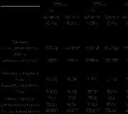
Semiconductor technology was then in its infancy and did not yet guarantee strict repeatability of parameters. Therefore, operable devices were sorted into groups of parameters (this is often done in our time). The inhabitants of Riga did the same, installing 8 types of TS R12-2 (Fig. 10). All other electrical and other characteristics are the same for all ratings (Fig. 11).
The production of TS R12-2 began simultaneously with the R&D “Hardness”, which ended in 1964 (GK Yu.V. Osokin). Within the framework of this work, an improved batch technology for mass production of germanium TCs based on photolithography and galvanic deposition of alloys through a photomask was developed. Its main technical solutions are registered as an invention of Osokin Yu.V. and Mikhalovich D.L. (A.S. No. 36845). Several articles by Yu.V. Osokina in collaboration with KB-1 specialists I.V. Nothing, G.G. Smolko and Yu.E. Naumov with a description of the design and characteristics of the R12-2 vehicle (and the subsequent R12-5 vehicle).
The design of the P12-2 was good for everyone, except for one thing - consumers did not know how to use such small products with the thinnest conclusions. Hardware firms, as a rule, had neither the technology nor the equipment for this. For the entire time of the release of R12-2 and R12-5, their use was mastered by NIIRE, the Zhiguli Radio Plant of the Ministry of Radio Industry, VEF, NIIP (since 1978 NPO Radiopribor) and a few other enterprises. Understanding the problem, the developers of the TS, together with NIIRE, immediately thought out the second level of design, which at the same time increased the density of the equipment layout.

Rice. 12. Module of 4 vehicles R12-2
In 1963, within the framework of the R&D “Kvant” (GK A.N. Pelipenko, with the participation of E.M. Lyakhovich), the design of the module was developed in NIIRE, in which four TS R12-2 were combined (Fig. 12). From two to four R12-2 TSs (in a case) were placed on a microboard made of thin fiberglass, which together implement a certain functional unit. Up to 17 leads were pressed onto the board (the number varied for a specific module) 4 mm long. The microplate was placed in a stamped metal cup 21.6 × 10 in size. 6.6 mm and a depth of 3.1 mm and filled with a polymer compound. The result is a hybrid integrated circuit (GIS) with double sealed elements. And, as we said, it was the first GIS in the world with two-level integration, and, perhaps, the first GIS in general. Eight types of modules were developed with the common name "Quantum", which performed various logical functions. As part of such modules, R12-2 vehicles remained operational under the influence of constant accelerations up to 150 g and vibration loads in the frequency range of 5–2000 Hz with acceleration up to 15 g.
The Kvant modules were first produced by the experimental production of NIIRE, and then they were transferred to the Zhiguli Radio Plant of the USSR Ministry of Radio Industry, which supplied them to various consumers, including the VEF plant.
TS R12-2 and Kvant modules based on them have proven themselves well and have been widely used. In 1968, a standard was released that established a unified system of designations for integrated circuits in the country, and in 1969 - General specifications for semiconductor (NP0.073.004TU) and hybrid (NP0.073.003TU) ICs with a unified system of requirements. In accordance with these requirements, the Central Bureau for the Application of Integrated Circuits (TsBPIMS, later TsKB "Dayton", Zelenograd) on February 6, 1969 approved new technical specifications for the TS ShT3.369.001-1TU. At the same time, the term “integrated circuit” of the 102 series first appeared in the designation of the product. In fact, it was one IC, sorted into four groups by output voltage and load capacity.

Rice. 13. IC series 116 and 117
And on September 19, 1970, the technical specifications AB0.308.014TU for the Kvant modules, which received the designation IS of the 116 series, were approved at TsBPIMS (Fig. 13). The series included nine ICs: 1KhL161, 1KhL162 and 1KhL163 - multifunctional digital circuits; 1LE161 and 1LE162 - two and four logical elements 2NOT-OR; 1TP161 and 1TP1162 - one and two triggers; 1UP161 - power amplifier, as well as 1LP161 - logical element "prohibition" for 4 inputs and 4 outputs. Each of these ICs had from four to seven versions, differing in output signal voltage and load capacity, in total there were 58 IC ratings. Executions were marked with a letter after the digital part of the IS designation, for example, 1ХЛ161Ж. In the future, the range of modules expanded. The 116 series ICs were actually hybrid, but at the request of RZPP they were labeled as semiconductor (the first digit in the designation is “1”, hybrids should have “2”).
In 1972, by a joint decision of the Ministry of Electronic Industry and the Ministry of Radio Industry, the production of modules was transferred from the Zhiguli Radio Plant to RZPP. This eliminated the need to transport the 102-series ICs over long distances, so there was no need to encapsulate the die of each IC. As a result, the design of ICs of both the 102nd and 116th series was simplified: there was no need to package ICs of the 102 series in a metal cup filled with compound. The unpackaged ICs of the 102 series in a technological container were delivered to a neighboring shop for assembly of the ICs of the 116 series, mounted directly on their microboard, and sealed in the module case.
In the mid-1970s, a new standard for the IP notation system was released. After that, for example, IS 1LB021V received the designation 102LB1V.
The second IS and GIS of Yuri Osokin. solid circuit R12-5(IC series 103 and 117 )
By the beginning of 1963, as a result of serious work on the development of high-frequency n - p - n transistors, the team of Yu.V. Osokina accumulated a lot of experience with p-layers on the original n-germanium wafer. This and the availability of all the necessary technological components allowed Osokin in 1963 to start developing a new technology and design for a faster version of the TS. In 1964, by order of NIIRE, the development of the R12-5 TS and modules based on it was completed. According to its results, in 1965, the Palanga R&D was opened (GK Yu.V. Osokin, his deputy - D.L. Mikhalovich, completed in 1966). Modules based on P12-5 were developed within the framework of the same R&D “Kvant” as modules based on P12-2. Simultaneously with the technical specifications for the 102 and 116 series, the technical specifications ShT3.369.002-2TU for the 103 series ICs (R12-5) and AV0.308.016TU for the 117 series ICs (modules based on the 103 series ICs) were approved. The nomenclature of types and standard ratings of TS R12-2, modules on them and series IS 102 and 116 was identical to the nomenclature of TS R12-5 and IS series 103 and 117, respectively. They differed only in speed and manufacturing technology of the IC chip. The typical propagation delay time of the 117 series was 55 ns versus 200 ns for the 116 series.
Structurally, the R12-5 TS was a four-layer semiconductor structure (Fig. 14), where the n-type substrate and p + -type emitters were connected to a common ground bus. The main technical solutions for the construction of the R12-5 TS are registered as the invention of Osokin Yu.V., Mikhalovich D.L. Kaidalova Zh.A. and Akmensa Ya.P. (A.S. No. 248847). In the manufacture of the four-layer structure of TS R12-5, an important know-how was the formation of an n-type p-layer in the original germanium plate. This was achieved by diffusion of zinc in a sealed-off quartz ampoule, where the plates are located at a temperature of about 900 ° C, and zinc is located at the other end of the ampoule at a temperature of about 500 ° C. Further formation of the TS structure in the created p-layer is similar to TS R12-2. The new technology made it possible to get away from the complex shape of the TC crystal. Wafers with P12-5 were also ground from the back side to a thickness of about 150 μm with the preservation of part of the original wafer, then they were scribbled into separate rectangular IC crystals.

Rice. 14. Crystal structure of TS P12-5 from AS No. 248847. 1 and 2 - ground, 3 and 4 - inputs, 5 - output, 6 - power
After the first positive results in the manufacture of experimental vehicles R12-5, by order of KB-1, the Mezon-2 R & D was opened, aimed at creating vehicles with four R12-5s. In 1965, operating samples were obtained in a flat ceramic-metal case. But P12-5 turned out to be difficult to manufacture, mainly due to the difficulty of forming a zinc-doped p-layer on the original n-Ge wafer. The crystal turned out to be labor-intensive to manufacture, the percentage of yield is low, and the cost of the TS is high. For the same reasons, the R12-5 TS was produced in small volumes and could not displace the slower, but technologically advanced R12-2. And R&D “Mezon-2” did not continue at all, including due to interconnection problems.
By that time, Pulsar Research Institute and NIIME were already working on a wide front to develop planar silicon technology, which has a number of advantages over germanium, the main of which is a higher operating temperature range (+150°С for silicon and +70°С for silicon). germanium) and the presence of a natural protective SiO 2 film in silicon. And the specialization of RZPP was reoriented to the creation of analog ICs. Therefore, RZPP specialists considered the development of germanium technology for the production of ICs inappropriate. However, in the production of transistors and diodes, germanium did not give up its positions for some time. In the department of Yu.V. Osokin, already after 1966, RZPP developed and produced germanium planar low-noise microwave transistors GT329, GT341, GT 383, etc. Their creation was awarded the State Prize of the Latvian USSR.
Application

Rice. 15. Arithmetic unit on solid circuit modules. Photo from TS booklet dated 1965

Rice. 16. Comparative dimensions of the automatic telephone exchange control device, made on a relay and a vehicle. Photo from TS booklet dated 1965
The customers and first consumers of the R12-2 TS and modules were the creators of specific systems: the Gnom computer (Fig. 15) for the Kupol airborne system (NIIRE, GK Lyakhovich E.M.) and naval and civil automatic telephone exchanges (plant VEF, GK Misulovin L.Ya.). Actively participated in all stages of the creation of the R12-2, R12-5 vehicles and modules on them and KB-1, the main curator of this cooperation from KB-1 was N.A. Barkanov. They helped with financing, manufacturing of equipment, research of TS and modules in various modes and operating conditions.
TS R12-2 and modules "Quantum" based on it were the first microcircuits in the country. Yes, and in the world they were among the first - only in the USA they began to produce their first semiconductor ICs from Texas Instruments and Fairchild Semiconductor, and in 1964 IBM began producing thick-film hybrid ICs for its computers. In other countries, IP has not yet been thought about. Therefore, integrated circuits were a curiosity for the public, the effectiveness of their application made a striking impression and was played up in advertising. In the surviving booklet on the R12-2 vehicle from 1965 (based on already real applications) it says: “ The use of R12-2 solid circuits in on-board computing devices makes it possible to reduce the weight and dimensions of these devices by a factor of 10–20, reduce power consumption, and increase operational reliability. … The use of R12-2 solid circuits in the control and switching systems of information transmission paths of automatic telephone exchanges makes it possible to reduce the volume of control devices by about 300 times, as well as significantly reduce power consumption (by 30–50 times)” . These statements were illustrated by photographs of the Gnome computer arithmetic device (Fig. 15) and a comparison of the ATS rack manufactured at that time by the VEF plant based on a relay with a small block in the girl’s palm (Fig. 16). There were other numerous applications of the first Riga ICs.
Production
Now it is difficult to restore a complete picture of the production volumes of the 102 and 103 series ICs over the years (today RZPP has turned from a large plant into a small production and many archives have been lost). But according to the memoirs of Yu.V. Osokin, in the second half of the 1960s, production amounted to many hundreds of thousands a year, in the 1970s - millions. According to his personal records, in 1985, ICs of the 102 series were issued - 4,100,000 pieces, modules of the 116 series - 1,025,000 pieces, ICs of the 103 series - 700,000 pieces, modules of the 117 series - 175,000 pieces.
At the end of 1989 Yu.V. Osokin, then the general director of Alpha software, turned to the leadership of the Military-Industrial Commission under the Council of Ministers of the USSR (VPK) with a request to remove series 102, 103, 116 and 117 from production due to their obsolescence and high labor intensity (for 25 years, microelectronics is far from went ahead), but received a categorical refusal. Deputy Chairman of the Military Industrial Complex V.L. Koblov told him that the planes were flying reliably and a replacement was out of the question. After the collapse of the USSR, ICs of the 102, 103, 116 and 117 series were produced even before the mid-1990s, that is, for more than 30 years. Computers "Gnome" are still in the navigational cockpit of the "Il-76" and some other aircraft. “This is a supercomputer,” our pilots are not lost when their foreign colleagues are surprised to be interested in a unit that has never been seen before.
About priorities
Despite the fact that J. Kilby and R. Noyce had predecessors, they are recognized by the world community as the inventors of the integrated circuit.
R. Kilby and J. Noyce, through their firms, applied for a patent for the invention of the integrated circuit. Texas Instruments applied for the patent earlier, in February 1959, while Fairchild did so only in July of that year. But patent number 2981877 was issued in April 1961 to R. Noyce. J. Kilby sued and only in June 1964 received his patent number 3138743. Then there was a ten-year war of priorities, as a result of which (rare) "friendship won." Ultimately, the Court of Appeal upheld R. Noyce's claim to primacy in technology, but ruled that J. Kilby was the creator of the first working microchip. And Texas Instruments and Fairchild Semiconductor signed a technology cross-licensing agreement.
In the USSR, patenting inventions for authors did not give anything but trouble, an insignificant one-time payment and moral satisfaction, so many inventions were not formalized at all. And Osokin was in no hurry either. But for enterprises, the number of inventions was one of the indicators, so they still had to be registered. Therefore, Yu. Osokina and D. Mikhalovich received the USSR Author's Certificate No. 36845 for the invention of the TS R12-2 only on June 28, 1966.
And J. Kilby in 2000 became one of the Nobel Prize winners for the invention of IP. R. Noyce did not wait for world recognition, he died in 1990, and according to the situation, the Nobel Prize is not awarded posthumously. Which, in this case, is not entirely fair, since all microelectronics followed the path started by R. Noyce. Noyce's authority among specialists was so high that he even received the nickname "mayor of Silicon Valley", because he was then the most popular of the scientists working in that part of California, which received the unofficial name of Silicon Valley (W. Shockley was called "Moses of Silicon Valley") . And the path of J. Kilby (“hairy” germanium) turned out to be a dead end, and was not implemented even in his company. But life is not always fair.
The Nobel Prize was awarded to three scientists. Half of it was received by 77-year-old Jack Kilby, and the other half was divided between Academician of the Russian Academy of Sciences Zhores Alferov and Professor of the University of California at Santa Barbara, American of German origin Herbert Kremer, for "the development of semiconductor heterostructures used in high-speed optoelectronics."
Evaluating these works, the experts noted that "integrated circuits are, of course, the discovery of the century, which had a strong impact on society and the world economy." For the forgotten J. Kilby, the Nobel Prize was a surprise. In an interview with a magazine Europhysics News He admitted: " At that time, I was only thinking about what would be important for the development of electronics from an economic point of view. But I did not understand then that the decrease in the cost of electronic products will cause an avalanche growth of electronic technologies”.
And the work of Yu. Osokin was not evaluated not only by the Nobel Committee. They are also forgotten in our country, the country's priority in the creation of microelectronics is not protected. And he certainly was.
In the 1950s, a material basis was created for the formation of multi-element products - integrated circuits - in one monolithic crystal or on one ceramic substrate. Therefore, it is not surprising that almost simultaneously the idea of IP independently emerged in the minds of many specialists. And the speed of introducing a new idea depended on the technological capabilities of the author and the interest of the manufacturer, that is, on the presence of the first consumer. In this regard, Yu. Osokin was in a better position than his American colleagues. Kilby was new to TI, he even had to prove to the company's management the fundamental possibility of implementing a monolithic circuit by making its layout. Actually, the role of J. Kilby in the creation of IS comes down to re-educating the leadership of TI and provoking R. Noyce with his layout to take action. Kilby's invention did not go into serial production. R. Noyce, in his young and not yet strong company, went to the creation of a new planar technology, which really became the basis of subsequent microelectronics, but the author did not immediately succumb. In connection with the foregoing, both of them and their firms had to spend a lot of effort and time for the practical implementation of their ideas for building serially capable ICs. Their first samples remained experimental, and other microcircuits, not even developed by them, went into mass production. Unlike Kilby and Noyce, who were far from production, factory worker Yu. Osokin relied on the industrially developed semiconductor technologies of RZPP, and he had guaranteed consumers of the first TS in the form of the initiator of the development of NIIRE and the nearby VEF plant, which helped in this work. For these reasons, the first version of his vehicle immediately went into experimental, smoothly transferred into mass production, which continued continuously for more than 30 years. Thus, starting the development of the TS later than Kilby and Noyce, Yu. Osokin (not knowing about this competition) quickly caught up with them. Moreover, the work of Yu. Osokin is in no way connected with the work of the Americans, evidence of this is the absolute dissimilarity of his TS and the solutions implemented in it to Kilby and Noyce microcircuits. Texas Instruments (not Kilby's invention), Fairchild, and RZPP began production of their ICs almost simultaneously, in 1962. This gives full right to consider Yu. Osokin as one of the inventors of the integrated circuit on a par with R. Noyce and more than J. Kilby, and it would be fair to share part of the Nobel Prize of J. Kilby with Yu. Osokin. As for the invention of the first GIS with two-level integration (and possibly GIS in general), here the priority is A. Pelipenko from NIIRE is absolutely indisputable.
Unfortunately, it was not possible to find samples of TS and devices based on them, necessary for museums. The author will be very grateful for such samples or their photographs.
Large integrated circuit
Modern integrated circuits designed for surface mounting.

Soviet and foreign digital microcircuits.
integral(engl. Integrated circuit, IC, microcircuit, microchip, silicon chip, or chip), ( micro)scheme (IC, IC, m/s), chip, microchip(English) chip- a chip, a chip, a chip) - a microelectronic device - an electronic circuit of arbitrary complexity, made on a semiconductor crystal (or film) and placed in a non-separable case. often under integrated circuit(IC) understand the actual crystal or film with an electronic circuit, and under microchip(MS) - IP enclosed in a case. At the same time, the expression "chip components" means "surface mount components" in contrast to components for traditional soldering through holes on the board. Therefore, it is more correct to say "chip microcircuit", meaning a microcircuit for surface mounting. At the moment (year), most of the microcircuits are manufactured in surface-mounted packages.
Story
The invention of microcircuits began with the study of the properties of thin oxide films, which manifest themselves in the effect of poor electrical conductivity at low electrical voltages. The problem was that there was no electrical contact at the point of contact between the two metals, or it had polar properties. Deep studies of this phenomenon led to the discovery of diodes and later transistors and integrated circuits.
Design levels
- Physical - methods for implementing one transistor (or a small group) in the form of doped zones on a crystal.
- Electrical - a circuit diagram (transistors, capacitors, resistors, etc.).
- Logic - a logical circuit (logical inverters, elements OR-NOT, AND-NOT, etc.).
- Circuit and system level - circuit and system engineering circuits (flip-flops, comparators, encoders, decoders, ALUs, etc.).
- Topological - topological photomasks for production.
- Program level (for microcontrollers and microprocessors) - assembler instructions for the programmer.
Currently, most of the integrated circuits are developed using CAD, which allow you to automate and significantly speed up the process of obtaining topological photomasks.
Classification
Degree of integration
Purpose
An integrated circuit can have a complete, arbitrarily complex, functionality - up to a whole microcomputer (single-chip microcomputer).
Analog Circuits
- Signal generators
- Analog multipliers
- Analog attenuators and adjustable amplifiers
- Power Supply Stabilizers
- Control microcircuits of switching power supplies
- Signal converters
- Timing schemes
- Various sensors (temperature, etc.)
Digital Circuits
- Logic elements
- Buffer converters
- Memory modules
- (Micro)processors (including the CPU in a computer)
- Single-chip microcomputers
- FPGA - Programmable Logic Integrated Circuits
Digital integrated circuits have a number of advantages over analog ones:
- Reduced power consumption associated with the use of pulsed electrical signals in digital electronics. When receiving and converting such signals, the active elements of electronic devices (transistors) operate in the "key" mode, that is, the transistor is either "open" - which corresponds to a high level signal (1), or "closed" - (0), in the first case on transistor there is no voltage drop, in the second - no current flows through it. In both cases, the power consumption is close to 0, in contrast to analog devices, in which the transistors are in the intermediate (resistive) state most of the time.
- High noise immunity digital devices is associated with a large difference between high (for example, 2.5 - 5 V) and low (0 - 0.5 V) level signals. An error is possible with such interference, when a high level is perceived as low and vice versa, which is unlikely. In addition, in digital devices, it is possible to use special codes that allow you to correct errors.
- The large difference between high and low level signals and a fairly wide range of their allowable changes makes digital technology insensitive to the inevitable scatter of element parameters in integrated technology, eliminates the need to select and configure digital devices.
To work any more or less complex electronics, usually you need a lot of parts. When there are many of them, they can be "combined", say, into integrated circuits. What are they? How are they classified? How are they made and what signals are transmitted?
What are logic integrated circuits (ICs)
In fact, this is a microelectronic device that is based on a crystal of arbitrary complexity, which is made on a semiconductor film or wafer. It is placed in a non-separable case (although it can do without it, but only when it is part of a microassembly). The first integrated circuit was patented in 1968. This was a kind of breakthrough in the industry, although the provided device did not very much correspond to modern ideas in terms of its parameters. Integrated circuits are generally manufactured for surface mounting. Often, an IC is understood to mean only one crystal or film. The most widely used integrated circuit on a silicon wafer. It turns out that its application in industry has a number of advantages, for example, the efficiency of signal transmission.
Design levels

These devices are complex, which is beautifully displayed. Now they are created using special CAD systems that automate and significantly speed up production processes. So, when designing, it is worked out:
- Logic level (inverters, NAND, NOR and the like).
- System and circuit engineering (triggers, encoders, ALUs, comparators, etc. are being worked out);
- Electrical (capacitors, transistors, resistors and similar devices).
- Topological level - photomasks for production.
- Physical - how one transistor (or a small group) is implemented on a chip.
- Software - instructions for microcontrollers, microprocessors and FPGAs are created. A behavior model is developed using a vertical scheme.
Classification
Speaking about how integrated circuits are distinguished, it is impossible to choose only one parameter of the type of complexity of the technology in question. Therefore, as many as three were selected within the framework of the article.
Degree of integration

- Small integrated circuit. Contains less than a hundred elements.
- Medium integrated circuit. The number of elements fluctuates in the range of one hundred/thousand.
- Large integrated circuit. Contains from a thousand to 10,000 elements.
- They have over ten thousand elements.
As a rule, a large integrated circuit is often used for consumer devices. Previously used other categories:
- Ultra-large integrated circuit. It included those samples that could boast the number of elements in the range from 1 million to 1 billion.
- giga-large integrated circuit. This included samples, the number of elements of which exceeded 1 billion elements.
But they don't apply at the moment. And all the samples that were previously referred to as UBIS and GBIS are now passed as VLSI. In general, this has allowed significant savings in the number of groups, since the last two types are usually used specifically in large research centers, where computer systems operate, the power of which is measured in tens and hundreds of terabytes.
Manufacturing technology

In view of the different manufacturing possibilities, integrated circuits are also classified according to how they are made and from what:
1. Semiconductor. In them, all elements and connections are made on the same semiconductor chip. Semiconductor integrated circuits use materials such as silicon, germanium, gallium arsenide, and hafnium oxide.
2. Film. All elements and connections are made as films:
Thick-film.
Thin-film.
3. Hybrid. It has unpackaged diodes, transistors or other electronic active components. Passive (such as resistors, inductors, capacitors) are placed on a common ceramic substrate. All of them are placed in one sealed case.
4. Mixed. Here there is not only a semiconductor crystal, but also thin-film (or thick-film) passive elements that are placed on its surface.
Type of processed signal

And the third, most recent kind, is based on what signals the integrated circuit processes. They are:
- Analog. Here, the input and output signals change according to the law They can take on a value in the range from negative to positive supply voltage.
- Digital. Here, any input or output signal can have two values: a logical one or zero. Each of them corresponds to its predetermined voltage level. So, TTL-type microcircuits evaluate the range 0-0.4V to zero, and 2.4-5V to one. There may be other divisions, it all depends on the specific sample.
- Analog-digital. Combine the advantages and features of previous models. For example, they may contain signal amplifiers and analog-to-digital converters.
Legal Features
What does the legislation say about integrated circuits? In our country, the legal protection of the topologies of integrated circuits has been granted. By it is meant the geometric-spatial arrangement of a certain set of specific elements and the connections between them fixed on a certain material carrier (according to Article 1448 of the Civil Code of the Russian Federation). The author of the topology has the following intellectual rights to his invention:
- Copyright.
- Exclusive right.
In addition, other preferences may belong to the author of the topology, including the possibility of receiving remuneration for its use. has been operating for ten years. During this time, the inventor, or the person to whom this status has been assigned, can register the topology with the relevant intellectual property and patent service.
Conclusion

That's all! If you have a desire to assemble your own scheme, you can only wish success. But at the same time I want to draw your attention to one feature. If there is a desire to assemble a microcircuit, then it is necessary to thoroughly prepare for this process. The fact is that its creation requires exceptional cleanliness at the level of a surgical operating room, and besides, due to the smallness of the parts, it will not be possible to work with a soldering iron in the usual mode - all actions are carried out by machines. Therefore, at home, you can only create schemes. If you wish, you can purchase industrial developments that will be offered on the market, but it is better to leave the idea of making them at home without significant finances.
INTEGRATED CXEMA (IC, integrated circuit, microcircuit), a functionally complete microelectronic product, which is a set of electrically interconnected elements (transistors, etc.) formed in a semiconductor single-crystal wafer. ICs are the element base of all modern radio-electronic devices, computer equipment, information and telecommunication systems.
History reference. The IC was invented in 1958 by J. Kilby (Nobel Prize, 2000), who, without dividing the germanium single-crystal plate into separate transistors formed in it, connected them together with the thinnest wires, so that the resulting device became a complete electronic circuit. Half a year later, the American physicist R. Noyce realized the so-called planar silicon IC, in which, for each area of bipolar transistors (emitter, base and collector), metallized areas (the so-called contact pads) were created on the surface of the silicon wafer, and the connections between them were made by thin-film conductors. In 1959, the industrial production of silicon integrated circuits began in the USA; mass production of IP in the USSR was organized in the mid-1960s in the city of Zelenograd under the leadership of K. A. Valiev.
IS technology. The structure of a semiconductor IC is shown in the figure. Transistors and other elements are formed in a very thin (up to several microns) near-surface layer of a silicon wafer; a multi-level system of interconnections is created from above. With an increase in the number of IC elements, the number of levels increases and can reach 10 or more. Interelement connections must have low electrical resistance. This requirement is satisfied, for example, by copper. Between the layers of conductors are placed insulating (dielectric) layers (SiO 2, etc.). Up to several hundred ICs are formed simultaneously on one PP wafer, after which the wafer is divided into separate crystals (chips).
The technological cycle of manufacturing an IC includes several hundred operations, the most important of which is photolithography (PL). The transistor contains dozens of parts, the contours of which are formed as a result of PL, which also determines the configuration of the interconnections in each layer and the position of the conductive regions (contacts) between the layers. In the technological cycle, PL is repeated several dozen times. Each PL operation is followed by the operations of manufacturing transistor parts, for example, the deposition of dielectric, PP, and metal thin films, etching, doping by ion implantation into silicon, etc. Photolithography determines the minimum size (MR) of individual parts. The main PL tool is optical projection steppers-scanners, which perform step-by-step (from chip to chip) exposure of the image (illumination of the chip, on the surface of which a photosensitive layer - photoresist is applied, through a mask called photomask) with a decrease (4: 1) in size images in relation to the dimensions of the mask and with the scanning of the light spot within the same chip. MR is directly proportional to the wavelength of the radiation source. Initially, the g- and i-lines (436 and 365 nm, respectively) of the emission spectrum of a mercury lamp were used in PL setups. The mercury lamp was replaced by excimer lasers based on KrF (248 nm) and ArF (193 nm) molecules. The improvement of the optical system, the use of photoresists with high contrast and sensitivity, as well as special high-resolution techniques in the design of photomasks and steppers-scanners with a light source of 193 nm wavelength make it possible to achieve MR equal to 30 nm or less on large chips (with an area of 1-4 cm 2) with a capacity of up to 100 plates (diameter 300 mm) per hour. Advancement to the region of smaller (30-10 nm) MR is possible using soft X-rays or extreme ultraviolet (EUV) with a wavelength of 13.5 nm. Due to the intense absorption of radiation by materials at this wavelength, refractive optics cannot be used. Therefore, EUV steppers use reflective optics on X-ray mirrors. Patterns should also be reflective. EUV lithography is an analog of projection optical lithography, does not require the creation of a new infrastructure and provides high performance. Thus, by the year 2000, IC technology had overcome the 100 nm (MR) barrier and became nanotechnology.
The structure of the integrated circuit: 1- passivating (protective) layer; 2 - the top layer of the conductor; 3 - dielectric layer; 4 - interlevel connections; 5 - contact pad; 6 - MOSFETs; 7 - silicon wafer (substrate).
Development directions. ICs are divided into digital and analog. The main share of digital (logical) microcircuits is made up of processor ICs and memory ICs, which can be combined on a single chip (chip), forming a "system-on-a-chip". The complexity of an IC is characterized by the degree of integration, determined by the number of transistors on a chip. Prior to 1970, the degree of digital IC integration doubled every 12 months. This regularity (the American scientist G. Moore first drew attention to it in 1965) was called Moore's law. Moore later refined his law: doubling the complexity of memory circuits occurs every 18 months, and processor circuits - after 24 months. As the degree of IC integration increased, new terms were introduced: large IC (LSI, with the number of transistors up to 10 thousand), super-large IC (VLSI - up to 1 million), ultra-large IC (UBIS - up to 1 billion) and giant LSI (GBIS - more 1 billion).
There are digital ICs on bipolar (Bi) and on MOS (metal - oxide - semiconductor) transistors, including in the CMOS configuration (complementary MOS, i.e., complementary p-MOS and w-MOS transistors connected in series in the "source supply - point with zero potential"), as well as BiCMOS (on bipolar transistors and CMOS transistors in one chip).
An increase in the degree of integration is achieved by reducing the size of transistors and increasing the size of the chip; this reduces the switching time of the logic element. As the size decreased, the power consumption and the energy (the product of the power and the switching time) spent on each switching operation decreased. By 2005, the speed of the IS improved by 4 orders of magnitude and reached fractions of a nanosecond; the number of transistors on a single chip was up to 100 million pieces.
The main share (up to 90%) in world production since 1980 has been digital CMOS ICs. The advantage of such circuits is that in either of the two static states ("0" or "1") one of the transistors is closed, and the current in the circuit is determined by the current of the transistor in the off state I OFF. This means that if I OFF is negligible, the current from the power supply is consumed only in the switching mode, and the power consumption is proportional to the switching frequency and can be estimated by the relation Ρ Σ ≈C Σ N f U 2 load capacity at the output of the logic element, N - number of logic elements on the chip, f - switching frequency, U - supply voltage. Almost all of the power consumed is released as Joule heat, which must be removed from the crystal. In this case, the power consumed in switching mode is added to the power consumed in static mode (determined by the currents I OFF and leakage currents). With a decrease in the size of transistors, static power can become comparable to dynamic power and reach, in order of magnitude, 1 kW per 1 cm 2 of the crystal. The problem of high power dissipation makes it necessary to limit the maximum switching frequency of high-performance CMOS ICs to the range of 1-10 GHz. Therefore, to increase the performance of "systems-on-a-chip", additional architectural (so-called multi-core processors) and algorithmic methods are used.
At channel lengths of MOS transistors of the order of 10 nm, quantum effects begin to affect the characteristics of the transistor, such as longitudinal quantization (an electron propagates in the channel as a de Broglie wave) and transverse quantization (due to the narrowness of the channel), direct tunneling of electrons through the channel. The latter effect limits the possibilities of using CMOS elements in ICs, since it makes a large contribution to the total leakage current. This becomes significant at a channel length of 5 nm. CMOS ICs will be replaced by quantum devices, molecular electronic devices, etc.
Analog ICs make up a wide class of circuits that act as amplifiers, oscillators, attenuators, digital-to-analog and analog-to-digital converters, comparators, phase shifters, etc., including low-frequency (LF), high-frequency (HF) and microwave ICs. Microwave ICs are circuits with a relatively low degree of integration, which can include not only transistors, but also film inductors, capacitors, resistors. To create a microwave IC, not only the traditional silicon technology is used, but also the technology of heterojunction ICs based on Si - Ge solid solutions, A III BV compounds (for example, gallium arsenide and nitride, indium phosphide), etc. This allows you to achieve operating frequencies of 10-20 GHz for Si - Ge and 10-50 GHz and higher for microwave ICs on A III BV connections . Analog ICs are often used together with sensor and micromechanical devices, biochips, etc., which ensure the interaction of microelectronic devices with a person and the environment, and can be enclosed with them in one package. Such designs are called multi-chip or "system-in-package".
In the future, the development of IS will lead to a merger of the two directions and the creation of microelectronic devices of great complexity, containing powerful computing devices, environmental control systems and means of communication with a person.
Lit. see at st. Microelectronics.
A. A. Orlikovsky.
The content of the article
INTEGRATED CIRCUIT(IC), a microelectronic circuit formed on a tiny wafer (crystal, or "chip") of semiconductor material, usually silicon, that is used to control and amplify electrical current. A typical IC consists of many interconnected microelectronic components, such as transistors, resistors, capacitors, and diodes, fabricated on the surface of a chip. The sizes of silicon crystals range from about 1.3 x 1.3 mm to 13 x 13 mm. Advances in the field of integrated circuits have led to the development of technologies for large and very large integrated circuits (LSI and VLSI). These technologies make it possible to obtain ICs, each of which contains many thousands of circuits: more than 1 million components can be counted in one chip.
Integrated circuits have a number of advantages over their predecessors - circuits that were assembled from individual components mounted on a chassis. ICs are smaller, faster and more reliable; they are also less expensive and less prone to failure due to vibration, moisture and aging.
The miniaturization of electronic circuits was made possible by the special properties of semiconductors. A semiconductor is a material that has much greater electrical conductivity (conductivity) than a dielectric such as glass, but much less than conductors such as copper. In a semiconductor material such as silicon, there are too few free electrons in the crystal lattice at room temperature to provide significant conductivity. Therefore, pure semiconductors have low conductivity. However, the introduction of an appropriate impurity into silicon increases its electrical conductivity.
Dopants are introduced into silicon by two methods. For heavy doping or in cases where precise control of the amount of impurity introduced is not necessary, the diffusion method is usually used. The diffusion of phosphorus or boron is generally carried out in a dopant atmosphere at temperatures between 1000 and 1150° C. for half an hour to several hours. In ion implantation, silicon is bombarded with high-speed dopant ions. The amount of implantable admixture can be adjusted to within a few percent; accuracy is important in some cases, since the gain of the transistor depends on the number of impurity atoms implanted per 1 cm 2 of the base ( see below).
Production.
The fabrication of an integrated circuit can take up to two months because some areas of the semiconductor need to be doped with high precision. In a process called crystal growth or pulling, a cylindrical billet of high purity silicon is first produced. Plates with a thickness of, for example, 0.5 mm are cut from this cylinder. The wafer is ultimately cut into hundreds of small pieces, called chips, each of which is converted into an integrated circuit by the process described below.
The processing of chips begins with the manufacture of masks for each layer of the IC. A large-scale stencil is made, having the shape of a square with an area of approx. 0.1 m 2. A set of such masks contains all the constituent parts of the IC: diffusion levels, interconnection levels, etc. The entire resulting structure is photographically reduced to the size of a crystal and reproduced layer by layer on a glass plate. A thin layer of silicon dioxide is grown on the surface of a silicon wafer. Each plate is coated with a light-sensitive material (photoresist) and exposed to light transmitted through the masks. The unexposed areas of the photosensitive coating are removed with a solvent, and with the help of another chemical agent that dissolves silicon dioxide, the latter is etched from those areas where it is now not protected by the photosensitive coating. Variations of this basic manufacturing process are used in the fabrication of the two main types of transistor structures: bipolar and field-effect (MOS).
bipolar transistor.
Such a transistor has a structure like n-p-n or, much less often, like p-n-p. Usually the technological process begins with a plate (substrate) of heavily alloyed material p-type. A thin layer of lightly doped silicon is epitaxially grown on the surface of this wafer. n-type; thus, the grown layer has the same crystal structure as the substrate. This layer should contain the active part of the transistor - individual collectors will be formed in it. The plate is first placed in a boron vapor furnace. Boron diffusion into the silicon wafer occurs only where its surface has been etched. As a result, regions and windows are formed from the material n-type. The second high temperature process, which uses phosphorus vapor and another mask, serves to form contact with the collector layer. By conducting successive diffusions of boron and phosphorus, a base and an emitter are formed, respectively. The thickness of the base is usually a few microns. These tiny islands of conduction n- and p-types are connected in a common circuit by means of interconnects made of aluminum deposited from the vapor phase or deposited in a vacuum. Sometimes noble metals such as platinum and gold are used for these purposes. Transistors and other circuit elements such as resistors, capacitors, and inductors, along with appropriate interconnects, can be diffusion-formed in a wafer in a series of steps, resulting in a complete electronic circuit.
MOSFET.
The most widely used MOS (metal-oxide-semiconductor) - a structure consisting of two closely spaced areas of silicon n-type implemented on the substrate p-type. A layer of silicon dioxide grows on the surface of silicon, and on top of this layer (between regions n-type and slightly capturing them) a localized layer of metal is formed, which acts as a shutter. The two areas mentioned above n-types, called source and drain, serve as connectors for input and output, respectively. Through the windows provided in the silicon dioxide, metal connections are made to the source and drain. Narrow surface channel made of material n-type connects source and drain; in other cases, the channel may be induced - created under the action of a voltage applied to the gate. When a positive voltage is applied to the gate of an induced channel transistor, the layer below the gate p-type turns into a layer n-type, and the current, controlled and modulated by the signal applied to the gate, flows from the source to the drain. The MOSFET consumes very little power; it has high input impedance, low drain current, and very low noise. Because the gate, oxide, and silicon form a capacitor, such a device is widely used in computer memory systems ( see below). Complementary, or CMOS, circuits use MOSFETs as loads and do not consume power when the main MOSFET is in the inactive state.
After completion of processing, the plates are cut into pieces. The cutting operation is performed by a circular saw with diamond edges. Each crystal (chip, or IC) is then enclosed in one of several types of package. 25 µm gold wire is used to connect the IC components to the package's lead frame. Thicker frame leads allow you to connect the IC to the electronic device in which it will work.
Reliability.
The reliability of an integrated circuit is about the same as that of a single silicon transistor of equivalent shape and size. Theoretically, transistors can last for thousands of years without fail - one of the most important factors for applications such as rocket and space technology, where a single failure can mean complete failure of the ongoing project.
Microprocessors and minicomputers.
First presented to the public in 1971, microprocessors performed most of the basic functions of a computer on a single silicon IC, implemented on a 5x5 mm chip. Thanks to integrated circuits, it became possible to create minicomputers - small computers, where all functions are performed on one or more large integrated circuits. This impressive miniaturization has led to a dramatic reduction in the cost of computing. Minicomputers currently being produced under $1,000 are as powerful as the first very large computers, which cost up to $20 million in the early 1960s. Microprocessors are used in communications equipment, pocket calculators, wrist clocks, TV selectors, electronic games, automated kitchen and banking equipment, automatic fuel control and exhaust gas aftertreatment in cars, as well as in many other devices. Most of the $15 billion global electronics industry relies on integrated circuits in one way or another. On a global scale, integrated circuits are used in equipment, the total cost of which is many tens of billions of dollars.
Computer storage devices.
In electronics, the term "memory" usually refers to some device designed to store information in digital form. Among the many types of memory devices (RAM), consider random access memory (RAM), charge-coupled devices (CCD) and read-only memory (ROM).
For RAM, the access time to any memory cell located on the chip is the same. Such devices can store 65,536 bits (binary ones, usually 0 and 1), one bit per cell, and are a widely used type of electronic memory; on each chip they have approx. 150 thousand components. RAM with a capacity of 256 Kbps (K = 2 10 = 1024; 256 K = 262 144) are produced. In memory devices with sequential sampling, the circulation of the stored bits occurs as if along a closed pipeline (in CCDs, this type of sampling is used). In a CCD, which is a specially configured IC, packets of electrical charges can be placed under tiny metal plates located at short distances from each other, electrically isolated from the chip. Charge (or lack thereof) can thus travel through a semiconductor device from one cell to another. As a result, it becomes possible to remember information in the form of a sequence of ones and zeros (binary code), as well as access to it when required. Although CCDs cannot compete with RAM in terms of speed, they are capable of processing large amounts of information at a lower cost, and they are used where random access memory is not required. The RAM implemented on such an IC is volatile, and the information recorded in it is lost when the power is turned off. Information is entered into the ROM during the production process and stored permanently.
The development and production of new types of IS do not stop. Erasable programmable ROM (EPROM) has two shutters stacked one above the other. When voltage is applied to the upper gate, the lower one can acquire a charge, which corresponds to 1 binary code, and when switching (reversing) the voltage, the gate can lose its charge, which corresponds to 0 binary code.