Pal ntsc systems. PAL or NTSC - which is better, what's the difference? Television broadcast standards
All this is almost a thing of the past. PAL and NTSC belong to analog television, which is slowly being replaced by digital everywhere and irrevocably. However, some time ago, these abbreviations were familiar to everyone who watched or shot video at home: discrepancies in recording standards led to equipment failure to play. Today the problem is not so acute: decoders are used if necessary. And yet, at one time, many copies were broken about the question of the differences between PAL and NTSC, especially considering the strict territorial reference: PAL belonged to Europe, NTSC to the USA and Japan. This alone caused controversy about what was best for a Soviet-Russian person. However, there is no answer to this question and there cannot be: taste and color always take precedence, and neither PAL nor NTSC were broadcast in Russia - SECAM reigns here.
PAL- a color analogue television system adopted in a number of countries in Europe, Africa, and Australia.
NTSC- a color analog television system adopted in the USA, Japan, South Korea and some other Asian countries.
Comparison of PAL and NTSC
Actually, the difference between PAL and NTSC is solely in the specifics of technology. Most video equipment models are omnivorous: they are capable of receiving a signal and reproducing an image of any of the three standards without distortion. First of all, you should pay attention to the horizontal scanning frequency: for PAL 625 lines, for NTSC - 525. Accordingly, the resolution is higher with the European system. But the frame rate is the opposite, 30 Hz versus 25 Hz.
To the eye, the differences between PAL and NTSC are noticeable in the quality of color reproduction. Technically more complex NTSC allows for color distortion, while PAL gives a picture that is close to natural. NTSC is sensitive to phase distortions of the signal and amplitude fluctuations, therefore the predominance of red, for example, or color replacement for it is common. In PAL, which appeared later, these shortcomings were eliminated, however, this was done at the expense of the clarity of the resulting image. In addition, the PAL receiver is more complex in configuration; it contains a delay line; therefore, the assembly cost is higher.
The PAL standard today exists in many varieties, different in specificity. NTSC is represented by three, one of which, NTSC N, corresponds to PAL N, differing almost in no way, so the names turned out to be interchangeable. Valid in Japan own format NTSC J
It's all about television. However, abbreviations are very familiar to gamers, and they are biased towards this issue. Or they treated it because the phenomenon had lost its relevance. Some years ago, game console manufacturers and game developers took into account the sales region when releasing content in either PAL or NTSC format. The consoles only recognized their own, refusing to work with strangers. Therefore, the game was localized not only through translation, but also by coding in accordance with the standard. Sometimes, along the way, something was changed or cut out in it, so that the same release in Europe and the USA could differ, and significantly. Those who could choose (and then owners of consoles without region lock) often chose PAL - because the resolution and color quality are slightly higher. But the games could slow down slightly. Naturally, there was no unanimity on this issue. Today, division by region is still relevant for some models of game consoles, but with chips (thanks to the craftsmen) and cross-platform it is not a problem.
TheDifference.ru determined that the difference between the PAL format and NTSC is as follows:
PAL is the standard for European countries, NTSC is for the USA, Japan and some Asian countries.
Scanning frequency for PAL - 625 lines, NTSC - 525.
Frame rate for PAL - 25 Hz, for NTSC - 30 Hz.
NTSC allows for distortion in color reproduction; PAL has lower image clarity.
Games and game consoles differ by sales region: NTSC for the USA, PAL for Europe.
2 years ago

PAL, SECAM and NTSC. This is the name of television standards, that is, formats. The SECAM standard is a television format that has found use in Russia. But not only that. It is also used in Eastern European countries and France. It is from the French “SEquential Couleur Avec Memoire” that its name comes.
SECAM provides for decomposition of a television frame into 625 lines, frame frequency 50 Hz. Since the frame rate and number of lines correspond to the PAL standard, nothing prevents you from viewing the video in monochrome SECAM format on a PAL standard video player, as well as vice versa.
Basic television standard in Europe it is PAL. It is also used in the UK, Australia and South Africa. The name comes from "Phase Alternate Line".
The PAL standard uses a method by which color is added to the television signal of black and white. It produces 625 lines on the screen at 25 frames per second. Similar to the NTSC system, it uses interlaced scanning.
The NTSC standard is a standard for video recording and television broadcasting. Found application in the USA, Japan and other countries. The specification for the NTSC standard was defined in 1952 by the National Television Standards Committee, which is where the name came from.
The standard defines a method for encoding information into a composite video signal. 16 million supported different colors. Today, new varieties of the NTSC standard “Super NTSC” and “16x9” are already being developed. They will be part of the MPEG standard and the DVD development standard.
The SECAM system is today, as already mentioned, the main color analogue television system in Russia. The main parameters of domestic television of this standard are determined within the framework of GOST 7845-92. After the collapse of the USSR in Eastern Europe, the SECAM system gradually began to supplant the PAL system.
Video equipment of the SECAM standard today, in fact, is not produced anywhere on the planet. All video production operates in the PAL system in European standard decomposition, and after transcoding the SECAM signal is broadcast.
When will Russian broadcasting switch to the PAL system? This issue has been repeatedly raised by experts, but the country is still full of television receivers that support the only SECAM standard.
Currently broadcast in Russia analogue broadcasting television channels maintained in the SECAM system. At the same time, the vast majority of analog television channels in cable broadcasting networks. Among them are those that are presented in the open air. They are transmitted in the PAL system, which means they cannot be viewed on older Soviet TVs in color.
Unlike the black-and-white image transmission standard, which was more or less uniform throughout the world (only the distance between the image and sound transmission frequencies differed), there are several color television standards. The main color television systems are SECAM, PAL, NTSC. System SECAM accepted in countries former USSR, and also in France. System PAL adopted in Western European countries, except France. System NTSC adopted on the American continent and in Japan. Standards PAL And SECAM were developed on the basis of a single standard for black-and-white images and with the ability to receive a new television signal on old televisions, therefore they are partially compatible with each other (the image scan and brightness are encoded in the same way, but the color balance is encoded differently). Standard NTSC was developed independently of the old standard. Currently being finalized, and in some countries introducing digital standards, the advantage of which is increased picture resolution, increased picture frequency, as well as signal noise immunity. In Russia, the transition to digital broadcasting is planned for 2010.
NTSC standard
NTSC (National Television System Color) - the first color television system to find practical application. It was developed in the USA and already accepted for broadcasting in 1953, and currently broadcasting using this system is also carried out in Canada, most countries of Central and South America, Japan, South Korea and Taiwan. It was during its creation that the basic principles of color transmission in television were developed. This standard defines a method for encoding information into a composite video signal. According to standard NTSC, each video frame consists of 525 horizontal lines of screen along which an electron beam passes every 1/30 of a second. When drawing a frame, the electron beam makes two passes across the entire screen: first along the odd lines, and then along the even lines (interlacing). Supports 16 million different colors. New versions of the NTSC standard "Super NTSC" and "16 x 9" are currently being developed, which will be part of the MPEG standard and the DVD development standard
PAL standard
SECAM standard
System SECAM (SEquentiel Couleur A Memoire), like PAL, uses a 625-line screen at 25 frames per second. This system was originally proposed in France back in 1954, but regular broadcasting, after lengthy modifications, began only in 1967 simultaneously in France and the USSR. Currently, it is also accepted in Eastern Europe, Monaco, Luxembourg, Iran, Iraq and some other countries. The main feature of the system is the alternate transmission of color-difference signals through a line with further restoration in the decoder by repeating lines. However, in contrast to PAL And NTSC used frequency modulation subcarriers. As a result, color tone and saturation do not depend on illumination, but color fringing appears at sharp transitions in brightness. Usually, after the bright areas of the image, the fringing has blue, and after dark ones - yellow. In addition, as in the system PAL, vertical color clarity is halved.
Sources:
http://www.videodata.ru/palsecam.htm
http://ru.wikipedia.org/wiki/%D0%92%D0%B8%D0%B4%D0%B5%D0%BE
IEEE1394 interface
(FireWire, i-Link) is a high-speed serial bus designed for exchanging digital information between a computer and other electronic devices.
Various companies promote the standard under their own brands:
Apple - FireWire
Story
in 1986, members of the Microcomputer Standards Committee decided to combine the existing various options serial bus(Serial Bus)
in 1992, Apple began developing the interface
IEEE 1394 standard adopted in 1995
Advantages
Digital interface - allows you to transfer data between digital devices without loss of information
Small size - a thin cable replaces a pile of bulky wires
Easy to use - no terminators, device IDs or pre-installation
Hot pluggability - the ability to reconfigure the bus without turning off the computer
Low cost for end users
Various data transfer rates - 100, 200 and 400 Mbps (800, 1600 Mbps IEEE 1394b)
Flexible topology - equality of devices, allowing various configurations (the ability to “communicate” devices without a computer)
High speed - the ability to process multimedia signals in real time
Open architecture - no need to use special software
Availability of power directly on the bus (low-power devices can do without their own power supplies). Up to one and a half amperes and voltage from 8 to 40 volts.
Connect up to 63 devices.
IEEE 1394 bus can be used with:
Computers
Audio and video multimedia devices
Printers and scanners
Hard drives, RAID arrays
Digital video cameras and VCRs
IEEE 1394 Device Organization
IEEE 1394 devices are organized according to a 3-level scheme - Transaction, Link and Physical, corresponding to three lower levels OSI models.
Transaction Layer - routing of data streams with support for an asynchronous write-read protocol.
Link Layer - forms data packets and ensures their delivery.
Physical Layer - transformation digital information to analog for transmission and vice versa, control of the signal level on the bus, control of access to the bus.
Communication between PCI bus and Transaction Layer is implemented by Bus Manager. It assigns the type of devices on the bus, numbers and types of logical channels, and detects errors.
Data is transmitted in frames with a length of 125 μs. Time slots for channels are placed in the frame. Both synchronous and asynchronous operating modes are possible. Each channel can occupy one or more time slots. To transmit data, the transmitter device asks for a synchronous channel of the required bandwidth. If the transmitted frame contains the required number of time slots for a given channel, an affirmative response is received and the channel is granted.
FireWire Specifications
IEEE 1394
At the end of 1995, IEEE adopted a standard under serial number 1394. In digital Sony cameras The IEEE 1394 interface appeared before the adoption of the standard and was called iLink.
The interface was initially positioned for transmitting video streams, but manufacturers also liked it external drives, providing high throughput for modern high-speed disks. Today many motherboards, as well as almost all modern laptop models support this interface.
Data transfer rates - 100, 200 and 400 Mbit/s, cable length up to 4.5 m.
IEEE 1394a
In 2000, the IEEE 1394a standard was approved. A number of improvements have been made to increase device compatibility.
A wait time of 1/3 second has been introduced for bus reset until the transient process of establishing a reliable connection or disconnection of the device is completed.
IEEE 1394b
In 2002, the IEEE 1394b standard appeared with new speeds: S800 - 800 Mbit/s and S1600 - 1600 Mbit/s. The maximum cable length also increases to 50, 70 and when using high-quality fiber optic cables up to 100 meters.
The corresponding devices are designated FireWire 800 or FireWire 1600, depending on the maximum speed.
The cables and connectors used have changed. To achieve maximum speeds at maximum distances, the use of optics is provided, plastic for lengths up to 50 meters, and glass for lengths up to 100 meters.
Despite the change in connectors, the standards remained compatible, which can be achieved using adapters.
On December 12, 2007, the S3200 specification was introduced with a maximum speed of 3.2 Gbit/s.
IEEE 1394.1
In 2004, the IEEE 1394.1 standard was released. This standard was adopted to enable the construction of large-scale networks and dramatically increases the number of connected devices to a gigantic number of 64,449.
IEEE 1394c
Introduced in 2006, the 1394c standard allows the use of Cat 5e cable from Ethernet. It can be used in parallel with Gigabit Ethernet, that is, use two logical and mutually independent networks on one cable. The maximum declared length is 100 m, Maximum speed corresponds to S800 - 800 Mbit/s.
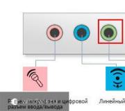
FireWire connectors
There are three types of connectors for FireWire:
4pin (IEEE 1394a without power) is used on laptops and video cameras. Two wires for signal transmission (information) and two for reception.
6pin (IEEE 1394a). Additionally two wires for power.
9pin (IEEE 1394b). Additional wires for receiving and transmitting information.
Integration
Audio and video equipment (digital CD, MD, VideoCD and DVD players, digital STB and Digital VHS) can already be integrated with computers and thus controlled. From this equipment it is possible to create systems - simple connection devices to each other using a single cable. After this, using a personal computer acting as a controller, you can perform the following operations: record from a CD player onto a mini-disc, store digital radio broadcasts received via STB, enter digital video into a personal computer for subsequent editing and editing. Of course, it remains possible to directly exchange data between audio and video equipment without using a computer or, conversely, exchange data between two computers without regard to audio or video, as in local networks based on traditional Ethernet technologies.
NEC recently announced the development of a chip designed to support hardware routing between two IEEE-1394-based networks and enable their interoperability in future IEEE-1394 broadband home multimedia networks. This dual-port chip also includes firmware that automatically configures the network and allows connections to be made to other network devices, including devices mobile communications. Thus, the home network can be extended beyond the boundaries of a specific home for a distance of up to one kilometer. Meanwhile, Sony continues to develop the concept of a home network based on the IEEE-1394 standard, and intends to support developments with a practical focus by releasing even more capacious, high-speed, compact, low-power components for a wide range of applications and subsequent integration into system chipsets. Today Sony is demonstrating new examples of consumer electronics that can create home network based on i.Link. All this architecture bears the proud name Home Audio/Video Interoperability (HAVi)). It seems that thanks to the efforts of Sony, we will soon really live, if not in a digital home, then in at least in a digital apartment. However, the IEEE-1394 standard, which is increasingly attracting the attention of not only manufacturers of audio and video devices, but also developers of equipment for personal computers, will no doubt soon become new network standard, bringing the coming digital era closer.
Published in the fall of 2000 operating system Microsoft Windows Millennium Edition built-in support for the first time local networks based on IEEE-1394 controllers. Such a network has a data transfer speed four times greater than Fast Ethernet and is very convenient for a home or small office. The only inconvenience when building such a network is the short maximum length of one segment (cable length up to 4.2 m). To eliminate this drawback, signal amplifiers - repeaters, as well as multiplier-hubs for several ports (up to 27) are produced. Recently, the new USB interface (version 2.0) has been actively competing with the IEEE-1394 interface, which provides data transfer at speeds of up to 480 Mbit/s versus the old 12 Mbit/s, that is, 40 times faster than the existing USB standard! The USB bus has become widespread due to its low cost and powerful support in the form of a controller built directly into chipsets for motherboards. At the same time, it was stated that high-speed USB 2.0 would also be implemented in the form of a controller built into the chipset (Intel ICH3). However, Microsoft has announced that it will prioritize support for the IEEE-1394 interface rather than USB 2.0, and, in addition, the asynchronous nature of USB transmission does not allow it to seriously compete with FireWire in the field of digital video.
Thus IEEE-1394 remains international standard inexpensive interface that allows you to connect all kinds of digital devices for entertainment, communication and computer technology into a household multimedia digital complex. In other words, all IEEE-1394 devices, such as digital photo and video cameras, DVD devices and other devices, fit perfectly both with personal computers equipped with a similar interface (both Mac and PC computers support it), and between yourself. This means that users can now transfer, process and save data (including images, sound and video) from high speed and virtually no degradation in quality. All these distinctive features IEEE-1394 make it the most attractive universal digital interface of the future.
http://www.videodive.ru/scl/ieee1394.shtml http://www.youtube.com/watch?v=3fLggMWeiVQ(video about how to remake an IEEE 1394 connector) http://www.youtube.com/watch?v=xrJA54IdREc(video about a laptop with IEEE 1394 connectors)
All this is almost a thing of the past. PAL and NTSC belong to analog television, which is slowly being replaced by digital everywhere and irrevocably. However, some time ago, these abbreviations were familiar to everyone who watched or shot video at home: discrepancies in recording standards led to equipment failure to play. Today the problem is not so acute: decoders are used if necessary. And yet, at one time, many copies were broken about the question of the differences between PAL and NTSC, especially considering the strict territorial reference: PAL belonged to Europe, NTSC to the USA and Japan. This alone caused controversy about what was best for a Soviet-Russian person. However, there is no answer to this question and there cannot be: taste and color always take precedence, and neither PAL nor NTSC were broadcast in Russia - SECAM reigns here.
Definition
PAL- a color analogue television system adopted in a number of countries in Europe, Africa, and Australia.
NTSC- a color analog television system adopted in the USA, Japan, South Korea and some other Asian countries.
Comparison
Actually, the difference between PAL and NTSC is solely in the specifics of technology. Most video equipment models are omnivorous: they are capable of receiving a signal and reproducing an image of any of the three standards without distortion. First of all, you should pay attention to the horizontal scanning frequency: for PAL 625 lines, for NTSC - 525. Accordingly, the resolution is higher with the European system. But the frame rate is the opposite, 30 Hz versus 25 Hz.
To the eye, the differences between PAL and NTSC are noticeable in the quality of color reproduction. Technically more complex NTSC allows for color distortion, while PAL gives a picture that is close to natural. NTSC is sensitive to phase distortions of the signal and amplitude fluctuations, therefore the predominance of red, for example, or color replacement for it is common. In PAL, which appeared later, these shortcomings were eliminated, however, this was done at the expense of the clarity of the resulting image. In addition, the PAL receiver is more complex in configuration; it contains a delay line; therefore, the assembly cost is higher.
The PAL standard today exists in many varieties, different in specificity. NTSC is represented by three, one of which, NTSC N, corresponds to PAL N, differing almost in no way, so the names turned out to be interchangeable. Japan has its own NTSC J format.
It's all about television. However, abbreviations are very familiar to gamers, and they are biased towards this issue. Or they treated it because the phenomenon had lost its relevance. Some years ago, game console manufacturers and game developers took into account the sales region when releasing content in either PAL or NTSC format. The consoles only recognized their own, refusing to work with strangers. Therefore, the game was localized not only through translation, but also by coding in accordance with the standard. Sometimes, along the way, something was changed or cut out in it, so that the same release in Europe and the USA could differ, and significantly. Those who could choose (and then owners of consoles without region lock) often chose PAL - because the resolution and color quality are slightly higher. But the games could slow down slightly. Naturally, there was no unanimity on this issue. Today, division by region is still relevant for some models of game consoles, but with chips (thanks to the craftsmen) and cross-platform it is not a problem.
Conclusions website
- PAL is the standard for European countries, NTSC is for the USA, Japan and some Asian countries.
- Scanning frequency for PAL - 625 lines, NTSC - 525.
- Frame rate for PAL - 25 Hz, for NTSC - 30 Hz.
- NTSC allows for distortion in color reproduction; PAL has lower image clarity.
- Games and game consoles vary by sales region: NTSC for the US, PAL for Europe.
Systems NTSC, PAL, SECAM
As you know, people of different nationalities speak different languages. So with the advent of color television, “television languages” arose, that is, color television systems. There are only three of them NTSC, PAL and SECAM. The NTSC system has become widespread in countries with an alternating current frequency of 60 Hz (USA, Japan), the PAL and SECAM systems - in countries with an alternating current frequency of 50 Hz. Accordingly, the vertical scan frequency (field frequency) was chosen in such a way as to reduce the noticeability of interference from the electrical wiring of the primary network: for NTSC - 60 Hz, for PAL and SECAM - 50 Hz.
As soon as they were developed various systems color television, there was a need to transfer video materials from one system to another - transcoding, and if we talk about transcoding from a 50 Hz to 60 Hz system or vice versa - standard conversion.
The basis of analog color television is the PCTS - a full color television signal (or composite video signal), which contains information about brightness and color. In the English-language literature, the abbreviations CCVBS and CCVS are used to designate it (each company calls the signal in its own way and each believes that it is right).
It is known that any color can be obtained by “turning on” red (Red), green (Green) and blue (Blue) light sources (or RGB for short) in the required proportion. They are called primary colors for additive color synthesis. A television screen is made up of small RGB elements. But RGB signals were not chosen for color television transmission. Instead, all systems are based on the transmission of brightness signals Y and color difference signals U and V. Strictly speaking, for each system color difference signals have their own letter designations, for example, for PAL - V and U, for NTSC - I and Q, for SECAM - Dr and Db. But, as a rule, all original articles on television equipment, microcircuits, etc. use the term RGB to refer to primary color signals and YUV to refer to color difference signals. The RGB and YUV signals are interconnected by a unique relationship (system of equations), which is called a matrix. It looks like this:
|
R |
G |
B |
|
|
Y |
0,299 |
0,587 |
0,114 |
|
R-Y |
0,701 |
0,587 |
0,114 |
|
B-Y |
0,299 |
0,587 |
0,114 |
Moreover, the multipliers (normalizing coefficients) for U and V in each system are different:
PAL: V = 0.877 (R-Y), U = 0.493 (B-Y);
NTSC: I = V cos 33° - U sin 33°, Q = V sin 33° + U cos 33°;
SECAM: Dr = -1.9 x (R-Y), Db = 1.5 x (B-Y).
So why didn’t any of the developers of television systems follow the seemingly natural path and begin transmitting signals from the main RGB colors? There are several reasons for this, but perhaps the main two:
First, color television systems must remain compatible with the original black-and-white television systems so that color programs can be viewed normally (or nearly so) on a black-and-white television;
Secondly, the color television system should not have required a wider frequency band for broadcasting than source system black and white television.
How did you manage to transmit additional color information without expanding the video signal bandwidth (that is, without increasing the amount of transmitted information)? Is this possible? Strictly speaking, no. Each color television system is an example of a more or less successful compromise between trade-offs in the quality of luminance signal transmission and gains from the skillful use of the resulting bandwidth for color signal transmission. Obviously, the PCTS must carry information about brightness and color. But if you simply add Y, U and V to introduce color difference signals, then it will be impossible to separate them in the future. The main task is to mix the brightness and color signals without mutual interference and separate them without error. But by what criteria can you distinguish brightness from color in a video signal?
This problem was solved by the feature human vision. It turned out that information about brightness is perceived by some photoreceptors of the eye - rods, and about color by others - cones (in television terminology, in YUV format). Moreover, the resolution of rods is much higher than that of cones. That is, if in the image the brightness contours are clearly marked, but the colors are “smeared,” then the human eye is guided by the brightness component, without noticing the “smear.” For example, cartoon characters in children's coloring books, even painted over by an unsteady child's hand, look quite neat and delight the parent's eye. But the typographic black outline gives this neatness to the drawing!
So, the brightness signal Y must be transmitted clearly, the color difference signals UV can be transmitted somewhat “smeared” (in a smaller frequency band) - the image will not suffer from this (or rather, the human eye will not notice it). To do less damage to clarity transmitted image, it was decided to use part of the high-frequency spectrum of the brightness signal to transmit color-difference signals. A special notch filter attenuates the luminance signal at a selected frequency and forms a “gap” in its frequency response. Often in specialized literature such a filter is called notch, which translated from English means “notch”. And the color-difference signals go to a low-pass filter, which limits their spectrum, then to a modulator, which shifts them to a given area of the frequency range (the modulation result is called the “chrominance subcarrier”), and then to the mixer, where the subcarrier fits into the “slot” prepared for it " in the spectrum of the brightness signal. The described method of luminance signal rejection, low-pass filtering and modulation of color-difference signals and addition of luminance and chrominance signals is the same for all color television systems. However, this is where the similarities end, and further each of the standards and their inherent advantages and disadvantages will be considered separately.
NTSC system
The NTSC standard was designed for a frame rate of 60 Hz (more precisely 59.94005994 Hz), 525 lines. To transmit chrominance, quadrature modulation with subcarrier suppression is used (that is, there is no chrominance subcarrier in uncolored areas). For modulation, a color subcarrier frequency of 3579545.5 Hz is used, which allows you to “place” 455 (odd number) half-cycles of the subcarrier frequency in one television line. Thus, in two adjacent NTSC lines, the chrominance subcarriers are in antiphase, and on the TV screen, the interference from the subcarrier looks like a small chessboard and is relatively invisible. It should be noted that if the television line had an even number of subcarrier half-cycles, the interference would look like a stationary vertical grid and its visibility would be much higher. The applied method of reducing the noticeability of interference (each “bright” point on the screen is surrounded by “dark” ones and vice versa) is also based on the properties of human vision: from a certain distance the eye stops perceiving each point, but sees a uniformly luminous screen - this is called “averaging” or “filtering” ". Since each point is surrounded by others not only from the sides, but also from above and below, such filtering is called “two-dimensional”. Note that a notch filter (which selects a "notch") or a low-pass filter (which rejects all frequencies above the cutoff frequency), which is typically used to separate luminance and chrominance signals, performs only one-dimensional (horizontal) filtering. A feature of the NTSC system is that color information is transmitted not in the coordinate system (R-Y), (B-Y), but in the I, Q system, rotated relative to (R-Y), (B-Y) by 33°. In addition, the bandwidths for the I and Q signals were chosen differently - American engineers took into account that the human eye distinguishes small blue-green details worse than red ones, and decided to further save on color and gain on brightness.
Now - about quadrature modulation: what is it good and what is bad? As already mentioned, we cannot simply add the signals Y, U and V - we will not be able to separate them later. Therefore, it is first necessary to obtain a chrominance subcarrier by modulating the sinusoidal signal in such a way that its amplitude depends on the values of the signals U and V, and the phase (relative to the original sinusoid) depends on the ratio of the values of U and V to each other. Such a signal can already be added to the brightness signal, and then separated again. To do this, frequencies close to the frequency of the original sinusoid must first be attenuated in the brightness signal using a notch filter.
The luminance/chrominance separation in the NTSC system deserves special attention. It is noted that in one NTSC television line there is an odd number of half-cycles of the chromaticity subcarrier and, therefore, in two adjacent lines the subcarrier is in antiphase. Now let's assume that the image does not contain clear horizontal boundaries, that is, two adjacent lines are not very different from each other. In reality, this is a very loose assumption, which is not always true. Then, as a result of the summation of two adjacent lines, mutual suppression of the chrominance subcarriers will occur and, as a result, only a luminance signal of double amplitude will remain. By subtracting two adjacent lines, the lumina signal will be suppressed (we previously assumed that the adjacent lines are "almost the same") and will leave a double-amplitude chrominance subcarrier. Thus, as a result of addition and subtraction operations, it was possible to absolutely correctly extract the brightness and color signals from the complete NTSC signal. This method of separating brightness/chrominance is called comb filtering. The comb filter allows you to obtain a brightness signal in the full frequency band, that is, it does not require rejection of the brightness signal during encoding! It should be noted, however, that the vertical resolution of the image deteriorates by a factor of two (!), since the brightness/color signals in each line are replaced by the average value over two adjacent lines. In addition, if there are horizontal boundaries in the image, the described method of separating brightness/chrominance simply stops working, which leads to a loss of vertical clarity, accompanied by the appearance of interference from the unfiltered chrominance subcarrier (the so-called “hanging dots”). Effective filtering is possible only with ideal timing characteristics of the video signal (adjacent lines must be located exactly one below the other without horizontal bounce, called “jitter”) and have an ideal dependence of the frequency and phase of the color subcarrier on the frequency and phase of the horizontal sync pulse. The comb filter is completely inapplicable for filtering a recording played back from a VCR (Philips Data sheet Product specification SAA7152 Digital Video Comb Filter (DCF) August 1996), and even the requirements Russian standard broadcasting is not enough for him. Therefore, it is impossible to use a comb filter in its pure form for processing real signals, and it will be possible to observe the ideally flat frequency response of the brightness signal that it produces only by connecting it to a television signal generator. Typically, a comb filter is always supplemented with a notch filter and an intelligent device for selecting the filtering method, depending on the quality of the video signal and image features. A notch filter for the NTSC system (as well as for the PAL system, which also uses phase modulation) can be relatively narrow-band, since with constant U and V signals the frequency of the chromaticity subcarrier is equal to the frequency of the unmodulated subcarrier and differs significantly from it only at sharp chromaticity transitions.
A few words should be said about the development of comb filters. Above we considered a two-dimensional (operating within one television field) comb filter. Two decades ago, a broadband television line delay device (namely, it is the basis of the comb filter) seemed to be the crown of scientific and technical thought. And now the existing frame memory blocks and the subcarrier phase alternation provided in NTSC not only in adjacent lines, but also in adjacent frames, make it possible to filter the image both vertically and horizontally, and in time. Note that time filtering is resistant to sharp boundaries in the image, but is sensitive to movement of boundaries in adjacent frames (motion).
Let's move on to decoding. The chrominance subcarrier, separated from the complete signal, is sent to the decoder to restore the values of U and V. Let us imagine a method of quadrature modulation with subcarrier suppression in the form of some “device” with an arrow, the length of which depends on the sum of the squares of U and V, and the deviation angle depends on the ratio of the values U and V to each other. In the special case when U=0 and V=0, the length of the arrow is also zero - this is called “subcarrier suppression”. Both the “device” and its pointer rotate with the frequency of the subcarrier, and in this rotating form they arrive at the decoder. The scale by which the deviation and arrow length (U and V) are determined is located in the decoder itself. In order for the speed of rotation of the scale to coincide with the speed of rotation of the “device”, a special reference burst of pulses is transmitted at the beginning of each line - a “burst”. In this way, the decoder adjusts the rotation speed and starting angle of the scale during the flash and reads the values for U and V during the active part of the line.
What is good and what is bad about quadrature modulation? The good thing is that in bright and lightly colored areas of the image (where the eye is most picky), the interference from the chromaticity subcarrier is small, since its range is small (the length of the arrow is short). The bad thing is that the transmission path of the television signal affects the rotation speed of the “device”, and in different parts of the line - in different ways. As a result, the initial correspondence (phase) between the angle of deflection of the “device” needle and the “precise time” signals is disrupted, which leads to a violation of the color tone of fragments of the transmitted image (for example, bright fragments acquire a reddish tint, and dark ones become greenish). In addition, the image as a whole may take on a tint. In this regard, NTSC is said to be sensitive to differential phase distortion. These are distortions that occur during the transmission of a television signal. In addition, the color tone is determined by the angle of deviation of the “device” needle relative to the dial, which rotates along with the “device” and is adjusted once at the beginning of the television line. If the dial lags or rushes, error accumulates toward the end of the line, causing the right side of the television screen to turn red or blue. Here are the main advantages and disadvantages of NTSC - a system built on precise mathematical calculations, which turned out to be the most vulnerable in real-life conditions.
PAL system.
The method of transmitting color in the PAL system is not much different from NTSC and is essentially an adaptation of NTSC for the 625 line/50 field frame format. The main difference (and significant improvement) in the PAL system is the Phase Alternating Lines. To decode chrominance in the PAL system, a chrominance decoder with a one-line delay line was developed. The peculiarity of a decoder with a delay line is that the color signals are reconstructed from the sum and difference of the subcarriers received in the current and previous lines. In this case, the error accumulated in the current line is equal in magnitude and opposite in sign to the error accumulated in the delayed line. The disadvantage of such a decoder is that the chrominance signal lags behind the luminance signal vertically (chrominance creep). In addition, the chrominance spectrum in PAL is much more complex than in NTSC, making the PAL comb filter much more complex. Typically, a notch/bandpass filter is used to separate luminance/chrominance in the PAL system. The PAL system is insensitive to differential phase distortion.
Striving to improve quality PAL systems and NTSC has led to the development of equipment in which the luminance signal and the chrominance subcarrier are carried on two separate wires and are not mixed anywhere and do not require separation. This two-wire method of transmitting a video signal is called S-Video or Y/C. S-Video allows you to use the full luminance frequency band (provides high horizontal resolution) and abandon the filtering that is inevitable for a composite signal when separating luminance/chrominance. Thus, the two-wire transmission method eliminates the frequency and phase distortions that accumulate during filtering. S-Video signals are not capable of over-the-air broadcasting. This is an in-studio standard with a wired connection method. It houses most studios using S-VHS equipment. We will consider the features of transcoding S-Video signals separately below.
SECAML system.
The SECAM color television system is fundamentally different from the NTSC and PAL systems. Just like in NTSC and PAL, chrominance information is transmitted to a subcarrier, which “fits” into a “slot” in the luminance signal. But to transmit color information, frequency modulation of the subcarrier is used. This means that each pair of U and V values corresponds to a pair of subcarrier frequencies. But if you mix (sum) two subcarriers, it will be impossible to separate them later. Therefore, assuming that the color in two adjacent lines is approximately the same, the subcarriers are transmitted in turn: in the current line - U, in next line- V, then again U and so on. The chrominance decoder contains a delay line - a device that delays the subcarrier by one line, and during decoding, two subcarriers are received at the frequency discriminator: one related to the current line directly, and the second from the previous line through the delay line. Hence the name of the system - SECAM (Sequence de Couleur A Memoire), that is, alternating colors with memory. The consequence of this color transmission mechanism (with decimation) is half the vertical color resolution and a downward shift of color relative to brightness. In addition, at sharp horizontal color boundaries (transitions from color “a” to color “b”), “false” colors appear, since the values of U and V are not averaged during transmission, but rather are thinned out. The reason for this effect is as follows: when transmitting color “a”, the RaGaBa values are restored from the YaUaVa values, respectively, when transmitting color “b”, the RbGbBb values are restored from the YbUbVb values. At the border of colors (more precisely, on the first line of another color), due to the delay of one of the chromaticity components in the decoder, RGB values are restored from the triple YbUaVb - for one field and (due to the alternation of U and V in the fields) from the triple YbUbVa - for another field. Note that the colors UaVb and UbVa are absent in both color "a" and color "b". On a monitor screen, these distortions are clearly visible when viewing horizontal color stripes, and on television broadcasts they are often visible in computer graphics, titles, etc. and look like separate lines flickering at a frequency of 25 Hz. To improve the transmission of small color details, differentiation (sharpening) of the edges of the U and V signals is applied (the so-called SECAM low-frequency correction), and in order to avoid excessive expansion of the frequency band of the low-frequency subcarrier, the corrected color-difference signals pass through a limiter. Thus, the SECAM system is fundamentally unable to correctly convey sharp color transitions. On the "vertical color bars" test signal, this effect appears as "gaps" between the bars and is especially noticeable between the green and magenta bars. To improve the signal-to-noise ratio of the chroma signal and optimize chrominance/luminance crosstalk, the modulated SECAM subcarrier is passed through a frequency-dependent circuit (called SECAM RF equalization or "bell"). In an RF-corrected signal, chroma edges (changes in color) are transmitted with more energy and therefore a better signal-to-noise ratio. However, this increases the visibility of the chrominance subcarrier, which appears as a characteristic “boiling” in the image immediately after the vertical color boundaries. You should pay attention to the features of the brightness/chrominance separation for the SECAM system. In the NTSC and PAL discussed above, the chrominance subcarrier is transmitted at the same frequency (for NTSC - 3.58 MHz, for PAL - 4.43 MHz). It is enough to install a filter tuned to this frequency to separate brightness and color. Moreover, in uncolored areas of the image (where the eye is most sensitive to interference), the subcarrier is suppressed and interference is fundamentally eliminated. The situation in the SECAM system is much more complicated. Firstly, there is no subcarrier suppression, that is, there is always interference from the subcarrier and it always needs to be filtered. Secondly, there is no way to isolate yourself from interference at any one frequency: SECAM frequency modulation occupies a band from 3.9 to 4.75 MHz, and the subcarrier frequency in a line of an image fragment depends only on the color of this fragment. In addition, the so-called "zero frequencies" for the U and V lines are different: 4.250 and 4.406 MHz, respectively. Thus, for reliable filtering of the brightness signal, it would be necessary to cut out a band from at least 3.9 to 4.75 MHz from the complete signal, and in fact, taking into account the finite steepness of the filters, it would be much wider. With this approach, it would be necessary to give up the ability to transmit SECAM in a complete signal small details images. As a compromise, and also taking into account the different null frequencies in the SECAM decoder, a tunable filter was used that switched the notch frequency between 4.250 and 4.406 MHz from line to line and thereby cleared the uncolored (most critical) areas of the image from the chrominance subcarrier. It was assumed that in the remaining areas of the image the unsuppressed subcarrier would be masked by intense coloring. In addition, the “brightness” details of the image that fall into the delay band of the tunable filter in one line will be missed by the filter in the next line and, therefore, the viewer will see them on the TV screen.
In the process of encoding/decoding a video signal, distortions and losses inherent in one of the systems inevitably arise. Even single transcoding, and even into the same system, already requires two encodings and two decodings - distortions and losses accumulate. When transcoding from one system to another, effects of the second kind begin to appear: the advantages that one system provides cannot be transferred and used in another. The simplest example, you need to make a composite PAL-YUV-PAL converter to overlay titles. If you extract information about the subcarrier phase of the original signal and use it in secondary encoding, then such transcoding (both theoretically and practically) can be done without loss.
To narrow the range of tasks under consideration and be closer to practice, let’s consider what needs to be transcoded in Russia.
Conversion from/to NTSC.
NTSC signal sources are: video discs, satellite broadcasts, broadcasting Japan (on Far East). There are practically no NTSC consumers in Russia. The amount of video that is transcoded (or perhaps more correctly "standardized") from/to NTSC to/from PAL and SECAM is small. Converting a sixty-hertz standard to a fifty-hertz standard and vice versa is a complex task, the difficulty of which lies in the need to change the decomposition standard. The newly received television signal must contain an image in those places of the television frame and at those points in time that were missed in the original signal. The simplest solution is to borrow the nearest raster line of the original signal, but this leads to “kinks” of object boundaries and “jerky” movements. Another solution is interline (two-dimensional) and interframe (three-dimensional, time) interpolation. It is free from "kinks" and "jerking", but leads to blurring of the boundaries of fast moving objects. The newest approach is the use of transducers with motion detectors. Such smart devices use algorithms to select areas in the frame and associate them with objects. From a sequence of frames, the direction, velocity, and acceleration of an object are calculated, and interpolation or predictive extrapolation is applied to the velocity and acceleration vectors. However, the described motion compensation algorithms only work in sufficiently simple cases, for example, with uniform linear motion. And how will they behave when processing the scene “a ball hitting a wall” (the magnitude and direction of the object’s speed, the acceleration of the object change abruptly, and at the moment of impact as a result of deformation, the shape of the object changes) or the scene “flight and rotation of a children’s ball” (one half whose color is green and the other red)?
Transcoding SECAM to PAL and PAL to SECAM..
In this case, a change in the decomposition standard is not required and the tasks of ensuring the widest bandwidth in the luminance and chrominance channels, the best signal-to-noise ratio, and the least luminance/chrominance crosstalk come to the fore. Secondary tasks include compensation for distortions introduced by the previous system, and processing that subjectively improves visual perception.
Transcoding SECAM to PAL is required, as a rule, for processing and editing archives recorded in the SECAM system on equipment PAL standard. There are studios that use SECAM to PAL conversion, PAL processing, and PAL to SECAM conversion to integrate local programming into national broadcasts, although this is not a successful solution. As noted above, when decoding SECAM in television receivers, a tunable “zero-frequency” notch filter SECAM is used. This filtering is acceptable for a TV, but for a transcoder it is completely insufficient. The fact is that the eye does not notice on the TV screen the fine chaotic residual grid of the unsuppressed SECAM subcarrier, but if a brightness signal of such a “degree of purification” is applied to the PAL encoder, then as a result of beating of the remnants of the SECAM subcarrier and the “new” PAL subcarrier in the colored areas of the image the interference in the form of a diagonal grid will be clearly visible. It is noteworthy that by manually rebuilding the SECAM notch filter, you can choose to clear one or another color in the transcoded image from interference. It is possible to filter the SECAM brightness signal (the subcarrier attenuation required during transcoding must be at least 40-42 dB) with traditional LC filters only by using a low-pass filter with a cutoff frequency of no higher than 3.2 MHz and a high slope. However, with such a bandwidth, fine image details are lost forever. Digital signal processing technologies have made it possible to create a tunable filter that effectively rejects the chrominance subcarrier in SECAM. Such a filter cuts out not only “zero frequencies”, but also constantly monitors the distribution of energy in the subcarrier band and cuts out the frequency where the energy is maximum, that is, the chrominance subcarrier. It should be noted that the technique for determining the bandwidth of a SECAM decoder with a digital tracking filter using a sweep generator is not applicable. When the sweep generator frequency falls within the expected range of SECAM subcarriers, it will be completely suppressed, and when leaving this range, the filter will be continuously tuned in the 3.9-4.75 MHz band. The brightness signal obtained after digital filtering is suitable for subsequent encoding in PAL. In this case, additional rejection of the brightness signal by a notch filter is not required, since the “extra” frequencies in the signal obtained as a result of decoding are already attenuated.
Transcoding PAL to SECAM is required in the following cases: when rebroadcasting a composite PAL signal received from a satellite; when broadcasting a VHS-quality composite signal from a PAL studio; when broadcasting an S-VHS-quality signal from a PAL studio (in the first two cases, the PAL composite signal is decoded, in the third - S-Video. In the first and second cases, special attention should be paid to the method of separating the brightness/chrominance of the composite signal and its additional filtering, in the third - to reject the color signal during encoding.
To separate the brightness/chrominance of a PAL signal received from a satellite, it may be justified to use a comb filter. In this case, the widest frequency band of the brightness signal can be obtained. However, such a filter is very sensitive to the temporal instability of the video signal. For example, with an acceptable difference in the duration of adjacent lines in broadcasting of 32 nanoseconds and a period of 225 nanoseconds of the PAL color subcarrier, the phase error in two adjacent lines will be 360°/225x32=51°. Thus, instead of the expected suppression of subcarriers in antiphase sin(a)+sin(a+180°)Ї0, the remainder of the unsuppressed subcarrier will be equal to sin(a)+sin(a+180°+51°). In other words, the comb filter will lose its functionality. The traditional notch filter works stably as when processing highly stable on-air reception, and when filtering the “boosted” video signal received from VHS video recorder, and easily provides suppression of the chrominance subcarrier no worse than 40-42 dB. It is best if the transcoder provides the ability to select a filtering method depending on the quality (time characteristics) of the transcoded PAL signal. As a rule, the luminance signal obtained after filtering already has attenuation in the vicinity of the frequency of 4.4 MHz, and when SECAM encoding additional notch may be required. When transcoding a component S-Video signal, you do not have to worry about interference from subcarrier penetration, but you need to pay close attention to forming the correct frequency response of the luma SECAM signal before summing it with the chrominance subcarrier in the encoder. The same attention should be paid to the brightness frequency response when transcoding a composite PAL signal if titles, logos, etc. are inserted into the transcoder. in YUV or RGB components, as well as if image enhancement/restoration mechanisms are used. The requirements for the frequency response of the brightness channel of the SECAM encoder are set out in OST 58-18-96 and are intended, on the one hand, to attenuate the high-frequency components of brightness so that they do not “obscure” the chrominance subcarrier, on the other hand, to bring fine details to the screen images, even in a weakened form.
In addition to the necessary properties and qualities described above, the transcoder can perform some additional functions, for example:
Separate gain control in RGB or YUV components for color correction;
Aperture one- or two-dimensional correction of brightness and chrominance signals to sharpen the vertical and/or horizontal boundaries of brightness and chrominance;
Adjusting the combination of brightness and color signals horizontally and vertically, which will allow you to “put in place” the color that has “moved out” as a result of multiple transcoding;
Noise reduction: median filter - to eliminate satellite "sparks", recursive - to suppress magnetic film noise, etc.
The Russian market offers transcoders and standard converters of both domestic and foreign origin. Among the companies specializing in their development and production, one cannot fail to mention: Snell&Wilcox, FOR.A, Vistek, JSC VNIITR, Profitt, ITM. Transcoders differ significantly both in price and in the capabilities they provide. In general, there is a clear relationship: the higher the price, the more opportunities. But it is impossible to give universal advice on which transcoder to choose “so that it suits us all,” as one of the advertisements says. For each specific case, you should choose a transcoder based on budget and the principle of minimal redundancy.