Using vlan technology to create a network. VLAN - Virtual Local Area Network
9) Routing: static and dynamic using the example of RIP, OSPF and EIGRP.
10) Network address translation: NAT and PAT.
11) First hop reservation protocols: FHRP.
12) Computer network security and virtual private networks: VPN.
13) Global networks and protocols used: PPP, HDLC, Frame Relay.
14) Introduction to IPv6, configuration and routing.
15) Network management and network monitoring.
P.S. Perhaps over time the list will be expanded.
In previous articles, we have already worked with many network devices, understood how they differ from each other and looked at what frames, packets and other PDUs consist of. In principle, with this knowledge you can organize a simple local network and work in it. But the world does not stand still. More and more devices are appearing that put a strain on the network or, even worse, create a security threat. And, as a rule, “danger” appears before “safety”. Now I will show this using a very simple example.
We will not touch on routers and different subnets for now. Let's say all nodes are on the same subnet.
Let me give you a list of IP addresses:
- PC1 – 192.168.1.2/24
- PC2 – 192.168.1.3/24
- PC3 – 192.168.1.4/24
- PC4 – 192.168.1.5/24
- PC5 – 192.168.1.6/24
- PC6 – 192.168.1.7/24


Who wants to see this in animation, open the spoiler (it shows ping from PC1 to PC5).
Network operation in one broadcast domain

Beautiful right? In previous articles we have already talked more than once about the operation of the ARP protocol, but that was last year, so I will briefly explain. Since PC1 does not know the MAC address (or link layer address) of PC2, it sends an ARP to reconnaissance so that it can tell it. It comes to the switch, from where it is relayed to all active ports, that is, to PC2 and to the central switch. From the central switch it will fly out to neighboring switches and so on until it reaches everyone. This is not a small amount of traffic caused by one ARP message. All network participants received it. Large and unnecessary traffic is the first problem. The second problem is security. I think they noticed that the message even reached the accounting department, whose computers were not involved in this at all. Any attacker connecting to any of the switches will have access to the entire network. In principle, this is how networks used to work. The computers were located in the same channel environment and were separated only by routers. But time passed and it was necessary to solve this problem at the link level. Cisco, as a pioneer, came up with its own protocol that tagged frames and determined belonging to a specific channel environment. It was called ISL (Inter-Switch Link). Everyone liked this idea and IEEE decided to develop a similar open standard. The standard was named 802.1q. It gained enormous popularity and Cisco decided to switch to it too.
And it is VLAN technology that is based on the operation of the 802.1q protocol. Let's start talking about her already.
In part 3 I showed what an ethernet frame looks like. Look at it and refresh your memory. This is what an untagged frame looks like.

Now let's take a look at the tagged one.

As you can see, the difference is that a certain Tag. This is what is interesting to us. Let's dig deeper. It consists of 4 parts.
1) TPID (Tag Protocol ID) or Tagged Protocol Identifier- consists of 2 bytes and for VLAN is always equal to 0x8100.
2) PCP (Priority Code Point) or priority value- consists of 3 bits. Used to prioritize traffic. Cool and bearded system administrators know how to manage it correctly and operate it when there is different traffic on the network (voice, video, data, etc.)
3) CFI (Canonical Format Indicator) or canonical format indicator- a simple field consisting of one bit. If it is 0, then this is the standard MAC address format.
4) VID (English VLAN ID) or VLAN identifier- consists of 12 bits and shows in which VLAN the frame is located.
I would like to draw attention to the fact that frame tagging is carried out between network devices (switches, routers, etc.), but frames are not tagged between the end node (computer, laptop) and the network device. Therefore, a network device port can be in 2 states: access or trunk.
- Access port or access port- a port located in a specific VLAN and transmitting untagged frames. Typically this is the port facing the user device.
- Trunk port or trunk port- port transmitting tagged traffic. Typically, this port rises between network devices.
I'm recruiting a team show vlan.

Several tables are lined up. In fact, only the very first one is important to us. Now I'll show you how to read it.
1 column is the VLAN number. Number 1 is initially present here - this is a standard VLAN, which is initially present on every switch. It performs another function, which I will write about below. There are also reserved ones from 1002-1005. This is for other channel media that are unlikely to be used today. You can't delete them either.
Switch(config)#no vlan 1005 Default VLAN 1005 may not be deleted.
When deleting, Cisco displays a message that this VLAN cannot be deleted. Therefore, we live and do not touch these 4 VLANs.
2nd column is the VLAN name. When creating VLANs, you can use your discretion to come up with meaningful names for them in order to identify them later. There is already default, fddi-default, token-ring-default, fddinet-default, trnet-default.
3 column- status. This shows what state the VLAN is in. At the moment, VLAN 1 or default is in the active state, and the next 4 are act/unsup (although active, they are not supported).
4 column- ports. This shows which VLANs the ports belong to. Now that we haven't touched anything yet, they are in default.
Let's start setting up the switches. It is good practice to give your switches meaningful names. That's what we'll do. I'm bringing the team.
Switch(config)#hostname CentrSW CentrSW(config)#
The rest are configured in the same way, so I’ll show you the updated topology diagram.

Let's start setting up with switch SW1. First, let's create a VLAN on the switch.
SW1(config)#vlan 2 - create VLAN 2 (VLAN 1 is reserved by default, so take the next one). SW1(config-vlan)#name Dir-ya - we get into the VLAN settings and give it a name.
VLAN has been created. Now let's move on to the ports. The FastEthernet0/1 interface looks at PC1, and FastEthernet0/2 looks at PC2. As mentioned earlier, frames between them must be transmitted untagged, so let’s transfer them to the Access state.
SW1(config)#interface fastEthernet 0/1 - proceed to setting up the 1st port. SW1(config-if)#switchport mode access - switch the port to access mode. SW1(config-if)#switchport access vlan 2 - assign the 2nd VLAN to the port. SW1(config)#interface fastEthernet 0/2 - proceed to setting up the 2nd port. SW1(config-if)#switchport mode access - switch the port to access mode. SW1(config-if)#switchport access vlan 2 - assign the 2nd VLAN to the port.
Since both ports are assigned to the same VLAN, they could still be configured as a group.
SW1(config)#interface range fastEthernet 0/1-2 - that is, select a pool and then set up the same. SW1(config-if-range)#switchport mode access SW1(config-if-range)#switchport access vlan 2
Configured access ports. Now let's configure a trunk between SW1 and CentrSW.
SW1(config)#interface fastEthernet 0/24 - proceed to setting up the 24th port. SW1(config-if)#switchport mode trunk - switch the port to trunk mode. %LINEPROTO-5-UPDOWN: Line protocol on Interface FastEthernet0/24, changed state to down %LINEPROTO-5-UPDOWN: Line protocol on Interface FastEthernet0/24, changed state to up
We immediately see that the port has been reconfigured. In principle, this is enough for work. But from a security point of view, only those VLANs that are really needed should be allowed for transmission. Let's get started.
SW1(config-if)#switchport trunk allowed vlan 2 - allow only the 2nd VLAN to be transmitted.
Without this command, all available VLANs will be transmitted. Let's see how the table has changed with the command show vlan.

A 2nd VLAN with the name Dir-ya has appeared and we see the ports fa0/1 and fa0/2 belonging to it.
To display only the top table, you can use the command show vlan brief.

You can further shorten the output if you specify a specific VLAN ID.

Or his name.

All VLAN information is stored in flash memory in the vlan.dat file.

As you noticed, none of the commands contain information about trunk. It can be viewed by another team show interfaces trunk.

There is information here about trunk ports and what VLANs they transmit. There is also a column here Native vlan. This is exactly the kind of traffic that should not be tagged. If an untagged frame arrives at the switch, it is automatically assigned to the Native Vlan (by default, and in our case, this is VLAN 1). Native VLAN is possible, but many say it needs to be changed for security reasons. To do this, in the trunk port configuration mode, you need to use the command - switchport trunk native vlan X, Where X- number of the assigned VLAN. We will not change this topology, but it is useful to know how to do it.
All that remains is to configure the remaining devices.
CenterSW:
The central switch is the connecting link, which means it must know about all VLANs. Therefore, we first create them, and then transfer all interfaces to trunk mode.
CentrSW(config)#vlan 2 CentrSW(config-vlan)# name Dir-ya CentrSW(config)#vlan 3 CentrSW(config-vlan)# name buhgalter CentrSW(config)#vlan 4 CentrSW(config-vlan)# name otdel -kadrov CentrSW(config)#interface range fastEthernet 0/1-3 CentrSW(config-if-range)#switchport mode trunk
Don't forget to save the config. Team copy running-config startup-config.
SW2(config)#vlan 3 SW2(config-vlan)#name buhgalter SW2(config)#interface range fastEthernet 0/1-2 SW2(config-if-range)#switchport mode access SW2(config-if-range)# switchport access vlan 3 SW2(config)#interface fastEthernet 0/24 SW2(config-if)#switchport mode trunk SW2(config-if)#switchport trunk allowed vlan 3
SW3:
SW3(config)#vlan 4 SW3(config-vlan)#name otdel kadrov SW3(config)#interface range fastEthernet 0/1-2 SW3(config-if-range)#switchport mode access SW3(config-if-range) #switchport access vlan 4 SW3(config)#interface fastEthernet 0/24 SW3(config-if)#switchport mode trunk SW3(config-if)#switchport trunk allowed vlan 4
Please note that we raised and configured the VLAN, but left the addressing of the nodes the same. That is, virtually all nodes are on the same subnet, but separated by VLANs. You can't do that. Each VLAN must be assigned a separate subnet. I did this solely for educational purposes. If each department sat in its own subnet, then they would be a priori limited, since the switch does not know how to route traffic from one subnet to another (plus this is already a limitation at the network level). And we need to limit departments at the link level.
I ping PC1 to PC3 again.

ARP is being used, which is what we need now. Let's open it.

Nothing new yet. ARP is encapsulated in ethernet.

The frame arrives at the switch and is tagged. Now there is not ordinary ethernet, but 802.1q. The fields that I wrote about earlier have been added. This TPID, which is equal to 8100 and indicating that it is 802.1q. AND TCI, which combines 3 fields PCP, CFI and VID. The number in this field is the VLAN number. Let's move on.

After the tag, it sends the frame to PC2 (since it is in the same VLAN) and to the central switch via the trunk port.

Since it was not strictly defined which VLAN types to pass through which ports, it will send to both switches. And here the switches, seeing the VLAN number, understand that they do not have devices with such a VLAN and boldly discard it.

PC1 is waiting for a response, but it never comes. You can see it under the spoiler in the form of animation.
Animation

Now the next situation. Another person is hired to join the directorate, but there is no room in the directorate’s office and they are temporarily asked to place a person in the accounting department. Let's solve this problem.

We connected the computer to FastEthernet port 0/3 of the switch and assigned the IP address 192.168.1.8/24.
Now I'll configure the switch SW2. Since the computer must be in the 2nd VLAN, which the switch does not know about, I will create it on the switch.
SW2(config)#vlan 2 SW2(config-vlan)#name Dir-ya
Next we configure the FastEthernet 0/3 port, which looks at PC7.
SW2(config)#interface fastEthernet 0/3 SW2(config-if)#switchport mode access SW2(config-if)#switchport access vlan 2
And the last thing is to configure the trunk port.
SW2(config)#interface fastEthernet 0/24 SW2(config-if)#switchport trunk allowed vlan add 2 - pay attention to this command. Namely, the keyword "add". If you do not add this word, you will erase all other VLANs allowed for transmission on this port. Therefore, if you already had a trunk raised on the port and other VLANs were transmitted, then you need to add it this way.
To make the frames flow beautifully, I’ll adjust the central switch CentrSW.
CentrSW(config)#interface fastEthernet 0/1 CentrSW(config-if)#switchport trunk allowed vlan 2 CentrSW(config)#interface fastEthernet 0/2 CentrSW(config-if)#switchport trunk allowed vlan 2,3 CentrSW(config) #interface fastEthernet 0/3 CentrSW(config-if)#switchport trunk allowed vlan 4
Check time. I send a ping from PC1 to PC7.


So far, the entire path is similar to the previous one. But from this moment (from the picture below) the central switch will make a different decision. He receives the frame and sees that it is tagged with the 2nd VLAN. This means that it should only be sent to where it is allowed, that is, to port fa0/2.


And now he comes to SW2. We open it and see that it is still tagged. But the next node is a computer and the tag must be removed. Click on “Outbound PDU Details” to see how the frame will leave the switch.

And indeed. The switch will send the frame in a “clean” form, that is, without tags.

ARP reaches PC7. We open it and make sure that the untagged frame PC7 recognizes itself and sends a response.

We open the frame on the switch and see that it will be sent tagged. Then the frame will travel the same way it came.


ARP reaches PC1, as evidenced by the check mark on the envelope. Now he knows the MAC address and uses ICMP.

We open the package on the switch and see the same picture. At the link layer, the frame is tagged by the switch. This will happen with every message.


We see that the package successfully reaches PC7. I will not show the way back, since it is similar. If anyone is interested, you can see the whole path in the animation under the spoiler below. And if you want to dig into this topology yourself, I’m attaching a link to the laboratory.
VLAN operation logic

This is, in principle, the most popular use of VLANs. Regardless of the physical location, you can logically combine nodes into groups, thereby isolating them from others. It is very convenient when employees physically work in different places, but must be united. And of course, from a security point of view, VLANs are not interchangeable. The main thing is that a limited circle of people have access to network devices, but this is a separate topic.
We achieved restrictions at the link level. Traffic no longer goes anywhere, but goes strictly as intended. But now the question arises that departments need to communicate with each other. And since they are in different channel environments, routing comes into play. But before we begin, let's put the topology in order. The very first thing we will put our hand to is addressing nodes. I repeat that each department must be in its own subnet. In total we get:
- Directorate - 192.168.1.0/24
- Accounting - 192.168.2.0/24
- HR department - 192.168.3.0/24

Once the subnets are defined, we immediately address the nodes.
- PC1:
IP: 192.168.1.2
Mask: 255.255.255.0 or /24
Gateway: 192.168.1.1 - PC2:
IP: 192.168.1.3
Mask: 255.255.255.0 or /24
Gateway: 192.168.1.1 - PC3:
IP: 192.168.2.2
Mask: 255.255.255.0 or /24
Gateway: 192.168.2.1 - PC4:
IP: 192.168.2.3
Mask: 255.255.255.0 or /24
Gateway: 192.168.2.1 - PC5:
IP: 192.168.3.2
Mask: 255.255.255.0 or /24
Gateway: 192.168.3.1 - PC6:
IP: 192.168.3.3
Mask: 255.255.255.0 or /24
Gateway: 192.168.3.1 - PC7:
IP: 192.168.1.4
Mask: 255.255.255.0 or /24
Gateway: 192.168.1.1
Nodes have now added a parameter such as a gateway address. They use this address when they need to send a message to a node located on a different subnet. Accordingly, each subnet has its own gateway.
All that remains is to configure the router, and I open its CLI. According to tradition, I will give a meaningful name.
Router(config)#hostname Gateway Gateway(config)#
Next we move on to setting up interfaces.
Gateway(config)#interface fastEthernet 0/0 - go to the required interface. Gateway(config-if)#no shutdown - enable it. %LINK-5-CHANGED: Interface FastEthernet0/0, changed state to up %LINEPROTO-5-UPDOWN: Line protocol on Interface FastEthernet0/0, changed state to up
Now attention! We enabled the interface, but did not assign an IP address to it. The fact is that only a link or channel is needed from the physical interface (fastethernet 0/0). The role of gateways will be performed by virtual interfaces or subinterfaces. Currently there are 3 types of VLAN. This means there will be 3 subinterfaces. Let’s start setting up.
Gateway(config)#interface fastEthernet 0/0.2 Gateway(config-if)#encapsulation dot1Q 2 Gateway(config-if)#ip address 192.168.1.1 255.255.255.0 Gateway(config)#interface fastEthernet 0/0.3 Gateway(config-if )#encapsulation dot1Q 3 Gateway(config-if)#ip address 192.168.2.1 255.255.255.0 Gateway(config)#interface fastEthernet 0/0.4 Gateway(config-if)#encapsulation dot1Q 4 Gateway(config-if)#ip address 192.168 .3.1 255.255.255.0
The router is configured. Let's go to the central switch and configure a trunk port on it so that it passes tagged frames to the router.
CentrSW(config)#interface fastEthernet 0/24 CentrSW(config-if)#switchport mode trunk CentrSW(config-if)#switchport trunk allowed vlan 2,3,4
The configuration is complete and let's move on to practice. I send a ping from PC1 to PC6 (that is, to 192.168.3.3).

PC1 has no idea who PC6 or 192.168.3.3 is, but knows that they are on different subnets (as he understands this is described in the previous article). Therefore, it will send the message through the default gateway, the address of which is specified in its settings. And although PC1 knows the IP address of the main gateway, it lacks a MAC address to be completely happy. And he launches ARP.


Please note. Once a frame arrives at CentrSW, the switch does not broadcast it to just anyone. It sends only to those ports where the 2nd VLAN is allowed to pass through. That is, on the router and on SW2 (there is a user sitting in the 2nd VLAN).

The router recognizes itself and sends a response (shown by an arrow). And pay attention to the bottom frame. When SW2 received ARP from the central switch, it similarly did not send it to all computers, but sent only PC7, which sits in the 2nd VLAN. But PC7 rejects it because it is not for him. Let's look further.


ARP reached PC1. Now he knows everything and can send ICMP. Let me draw your attention once again to the fact that the destination MAC address (link layer) will be the address of the router, and the destination IP address (network layer) will be the PC6 address.


ICMP reaches the router. He looks at his spreadsheet and realizes that he doesn't know anyone at 192.168.3.3. Discards the arriving ICMP and lets the ARP reconnoiter.


PC6 recognizes itself and sends a response.


The response reaches the router and it adds an entry in its table. You can view the ARP table with the command show arp.
Let's move on. PC1 is unhappy that no one is answering him and sends the following ICMP message.


This time ICMP arrives without problems. He will follow the same route back. I'll just show you the end result.

The first packet was lost (as a result of ARP), but the second arrived without problems.
Who is interested in seeing it in animation, welcome to the spoiler.
InterVLAN Routing

So. We have achieved that if nodes are in the same subnet and in the same VLAN, then they will go directly through the switches. In the case when you need to transmit a message to another subnet and VLAN, it will be transmitted through the Gateway router, which performs “inter-vlan” routing. This topology is called "router on a stick" or "router on a stick". As you understand, it is very convenient. We created 3 virtual interfaces and sent different tagged frames along one wire. Without using subinterfaces and VLANs, you would have to use a separate physical interface for each subnet, which is not at all profitable.
By the way, this question is discussed very well in this video (the video is about 3 hours long, so the link is linked to that exact moment in time). If after reading and watching the video you want to finish everything with your own hands, I am attaching a download link.
We have dealt with VLANs and move on to one of the protocols that works with it.
DTP (Dynamic Trunking Protocol) or in Russian dynamic trunk protocol- Cisco proprietary protocol used to implement trunk mode between switches. Although, depending on the state, they can also be consistent in access mode.
DTP has 4 modes: Dynamic auto, Dynamic desirable, Trunk, Access. Let's see how they fit together.
| Modes | Dynamic auto | Dynamic desirable | Trunk | Access |
|---|---|---|---|---|
| Dynamic auto | Access | Trunk | Trunk | Access |
| Dynamic desirable | Trunk | Trunk | Trunk | Access |
| Trunk | Trunk | Trunk | Trunk | No connection |
| Access | Access | Access | No connection | Access |
That is, the left column is the 1st device, and the top line is the 2nd device. By default, switches are in “dynamic auto” mode. If you look at the mapping table, two switches in the “dynamic auto” mode are matched to the “access” mode. Let's check this out. I'm creating a new lab and adding 2 switches.

I won't connect them yet. I need to make sure that both switches are in "dynamic auto" mode. I'll check with the team show interfaces switchport.


The result of this command is very large, so I trimmed it and highlighted the points of interest. Let's start with Administrative Mode. This line shows which of the 4 modes a given port on the switch operates in. Make sure that the ports on both switches are in “Dynamic auto” mode. And the line Operational Mode shows in which mode of operation they agreed to operate. We have not connected them yet, so they are in the “down” state.
I'll give you good advice right away. When testing any protocol, use filters. Disable the display of all protocols you don’t need.
I switch CPT to simulation mode and filter out all protocols except DTP.


I think everything is clear here. I connect the switches with a cable and, when the links are raised, one of the switches generates a DTP message.

I open it and see that it is DTP encapsulated in an Ethernet frame. He sends it to the multicast address “0100.0ccc.cccc”, which belongs to the DTP, VTP, CDP protocols.
And let me draw your attention to 2 fields in the DTP header.
1) DTP Type- here the sender inserts a proposal. That is, what mode does he want to conform to? In our case, he suggests agreeing on “access”.
2) Neighbor MAC address- in this field he writes the MAC address of his port.
He sends it and waits for a reaction from his neighbor.

The message reaches SW1 and it generates a response. Where it also negotiates the “access” mode, inserts its MAC address and sends it on its way to SW2.

DTP reaches successfully. In theory, they should have been agreed upon in the “access” mode. I'll check.


As expected, they agreed to the “access” mode.
Some people say that the technology is convenient and use it. But I highly recommend not using this protocol on your network. I’m not the only one who recommends this, and now I’ll explain why. The point is that this protocol opens a big security hole. I will open the laboratory in which the “Router on a stick” work was analyzed and add another switch there.

Now I’ll go into the settings of the new switch and hardcode the port to operate in trunk mode.
New_SW(config)#interface fastEthernet 0/1 New_SW(config-if)#switchport mode trunk
I connect them and see how they match.


That's right. The “dynamic auto” and “trunk” modes are coordinated into the trunk. Now we are waiting for someone to start being active. Let's say PC1 decided to send a message to someone. Generates an ARP and releases it onto the network.

Let's skip his path until he gets to SW2.

And here's the interesting part.

It sends it to the newly connected switch. I explain what happened. As soon as we have agreed on a trunk with him, he begins to send him all incoming frames. Although the diagram shows that the switch is discarding frames, this does not mean anything. You can connect any intercepting device (sniffer) to the switch or instead of the switch and calmly view what is happening on the network. It seems that he intercepted a harmless ARP. But if you look deeper, you can see that the MAC address “0000.0C1C.05DD” and the IP address “192.168.1.2” are already known. That is, PC1 gave himself away without thinking. Now the attacker knows about such a computer. In addition, he knows that he is sitting in the 2nd VLAN. Then he can do a lot of things. The most common thing is to replace your MAC address, IP address, quickly agree in Access and impersonate PC1. But the most interesting thing. After all, you may not understand this right away. Usually, when we specify the operating mode of a port, it is immediately displayed in the configuration. I enter show running-config.

But here the port settings are empty. I enter show interfaces switchport and scroll to fa0/4.

And here we see that the trunk has been agreed upon. show running-config does not always provide comprehensive information. Therefore, remember other commands as well.
I think it’s clear why you can’t trust this protocol. It seems to make life easier, but at the same time it can create a huge problem. So rely on the manual method. When setting up, immediately decide which ports will operate in trunk mode and which in access. And most importantly, always turn off reconciliation. So that switches do not try to agree with anyone. This is done with the “switchport nonegotiate” command.
Let's move on to the next protocol.
VTP (VLAN Trunking Protocol)- a proprietary protocol from Cisco, used for exchanging information about VLANs.
Imagine a situation where you have 40 switches and 70 VLANs. As a good idea, you need to manually create them on each switch and specify which trunk ports to allow transmission. This is a tedious and long process. Therefore, VTP can take on this task. You create a VLAN on one switch, and all others are synchronized with its base. Take a look at the following topology.

There are 4 switches here. One of them is a VTP server, and the other 3 are clients. Those VLANs that will be created on the server are automatically synchronized on clients. I'll explain how VTP works and what it can do.
So. VTP can create, modify and delete VLANs. Each such action causes the revision number to increase (each action increases the number by +1). Afterwards he sends out advertisements containing the revision number. Customers who receive this announcement compare their revision number with the one they received. And if the number that comes is higher, they synchronize their database with it. Otherwise, the advertisement is ignored.
But that's not all. VTPs have roles. By default, all switches operate as a server. I'll tell you about them.
- VTP Server. He can do everything. That is, creates, changes, deletes VLAN. If it receives an advertisement in which a revision is older than it, it is synchronized. Constantly sends out announcements and relays from neighbors.
- VTP Client- This role is already limited. You cannot create, change, or delete VLANs. All VLANs receive and synchronize from the server. Periodically informs neighbors about its VLAN base.
- VTP Transparent- this is such an independent role. Can create, change and delete VLANs only in its database. He does not impose anything on anyone and does not accept anything from anyone. If it receives some kind of advertisement, it passes it on, but does not synchronize it with its database. If in previous roles the revision number increased with each change, then in this mode the revision number is always 0.
We've read enough theory and let's move on to practice. Let's check that the central switch is in Server mode. Enter the command show vtp status.

We see that VTP Operating Mode: Server. You can also notice that the VTP version is 2nd. Unfortunately, CPT version 3 is not supported. The revision version is zero.
Now let's configure the lower switches.
SW1(config)#vtp mode client Setting device to VTP CLIENT mode.
We see a message that the device has entered client mode. The rest are configured in exactly the same way.
For devices to be able to exchange advertisements, they must be in the same domain. And there is a peculiarity here. If the device (in Server or Client mode) is not a member of any domain, then at the first advertisement received, it will go to the advertised domain. If the client is a member of a certain domain, then it will not accept advertisements from other domains. Let's open SW1 and make sure that it is not a member of any domain.

Let's make sure it's empty.
Now we go to the central switch and transfer it to the domain.
CentrSW(config)#vtp domain cisadmin.ru Changing VTP domain name from NULL to cisadmin.ru
We see a message that he has been transferred to the cisadmin.ru domain.
Let's check the status.

And indeed. The domain name has changed. Please note that the revision number is currently zero. It will change as soon as we create a VLAN on it. But before creating it, you need to switch the simulator to simulation mode to see how it generates ads. We create the 20th VLAN and see the following picture.

Once the VLAN is created and the revision number is increased, the server generates advertisements. He has two of them. First, let's open the one to the left. This advertisement is called “Summary Advertisement” or in Russian “summary advertisement”. This announcement is generated by the switch once every 5 minutes, where it talks about the domain name and the current revision. Let's see what it looks like.

In the Ethernet frame, pay attention to the Destination MAC address. It is the same as above when DTP was generated. That is, in our case, only those who have VTP running will respond to it. Now let's look at the next field.

Here's all the information. I'll go through the most important fields.
- Management Domain Name - the name of the domain itself (in this case cisadmin.ru).
- Updater Identity - identifier of the one who updates. The IP address is usually written here. But since the address was not assigned to the switch, the field is empty
- Update Timestamp - update time. The time on the switch has not been changed, so it is set to the factory time.
- MD5 Digest - MD5 hash. It is used to check credentials. That is, if the VTP has a password. We did not change the password, so the hash is the default.
I think this is clear. Separate header for each VLAN type. The list is so long that it doesn't fit on the screen. But they are exactly the same, except for the names. I won’t bother with what each code means. And in CPT they are more of a convention.
Let's see what happens next.

Clients receive advertisements. They see that the revision number is higher than theirs and synchronize the database. And they send a message to the server that the VLAN base has changed.

How the VTP protocol works

This is how the VTP protocol basically works. But it has very big disadvantages. And these are disadvantages in terms of security. I will explain using the example of the same laboratory. We have a central switch on which VLANs are created, and then via multicast it synchronizes them with all switches. In our case, he talks about VLAN 20. I suggest taking another look at its configuration.
Please note. A VTP message reaches the server, where the revision number is higher than its own. He understands that the network has changed and he needs to adapt to it. Let's check the configuration.

The configuration of the central server has changed and now it will broadcast exactly this.
Now imagine that we have not one VLAN, but hundreds. This is a simple way to install a network. Of course, the domain may be password protected and it will be more difficult for an attacker to cause harm. Imagine a situation where your switch is broken and you urgently need to replace it. You or your colleague run to the warehouse to buy an old switch and forget to check the revision number. It turns out to be higher than the others. You've already seen what happens next. Therefore, I recommend not using this protocol. Especially in large corporate networks. If you are using VTP version 3, then feel free to switch the switches to “Off” mode. If you are using version 2, then switch to “Transparent” mode. Add tags
VLAN(Virtual Local Area Network) - a virtual local area network, is part of a larger LAN. The simplest mechanism for isolating various subnets on Ethernet, WI-FI interfaces. In order to organize a VLAN, the network switch (Switch) must support VLAN technology and the 802.1q protocol.
Benefits of VLAN:
increases the number of broadcast domains, but reduces the size of each broadcast domain, which in turn reduces network traffic and increases network security (both effects are tied together due to the single large broadcast domain);
reduces the efforts of administrators to create subnets;
reduces the amount of equipment, since networks can be separated logically rather than physically;
improves the management of various types of traffic.
Terms:
Term untagged: only one VLAN can receive all packets not assigned to any VLAN (in 3Com, Planet, Zyxel terminology - untagged, in Cisco terminology - native VLAN). The switch will add tags of this VLAN to all received frames that do not have any tags.
Trunk A VLAN is a physical channel over which several VLAN channels are transmitted, which differ in tags (labels added to packets). Trunks are usually created between “tagged ports” of VLAN devices: switch-switch or switch-router. (In Cisco documents, the term “trunk” also refers to the combination of several physical channels into one logical one: Link Aggregation, Port Trunking). A router (layer three switch) acts as a network backbone for network traffic of different VLANs.
To put it simply, a vlan is a logical channel inside a physical channel (cable), and trunk is a set of logical channels (vlans) inside one physical channel (cable).
VLANs can be identified by:
Porto (most frequently used). VLANs based on port number allow you to identify a specific port in a VLAN. Ports can be defined individually, in groups, across entire rows, and even across different switches via a trunk protocol. This is the simplest and most commonly used method for defining VLANs. This is the most common use of port-based VLAN implementation when workstations use the TCP/IP Dynamic Configuration Protocol (DHCP).
MAC address - address (very rare). VLANs based on MAC addresses allow users to remain on the same VLAN even if the user moves from one location to another. This method requires the administrator to determine the MAC address of each workstation and then enter this information into the switch. This method can be very difficult to troubleshoot if the user has changed the MAC address. Any configuration changes must be approved by the network administrator, which may cause administrative delays.
User ID (very rare)
VLAN Linux and D-Link DGS-1100-08P
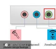
Setting up DGS-1100-08P. Let's connect to it at the first port. Let's assign it IP 10.90.91.2. Let's create 3 VLANs: vlan1 (port 1 (tagged)) for service use, that is, only for configuring the switch, vlan22 (port 1 (tagged); ports 2,3,4 (untagged)), vlan35 (port 1 (tagged); ports 5,6 (untagged)). Ports 7 and 8 are not used and are disabled via the Port Settings(Speed: Disabled) menu. We point out that in the future the D-Link DGS-1100-08P (IP 10.90.91.2) can only be managed via vlan1, that is, in our case, the system administrator must connect to the first port of the DGS-1100-08P (When connecting to a different port - the switch will not allow access to 10.90.91.2).
Create a VLAN named vlan22 bound to the eth4 network card port. Let's assign it IP:192.168.122.254. ip link add link eth4 name vlan22 type vlan id 22 ip addr add 192.168.122.254/ 24 dev vlan22 ifconfig vlan22 up
Service vlan only for configuring the switch:
Ip link add link eth4 name vlan44 type vlan id 1 ip addr add 10.90.91.254/ 24 dev vlan44 ifconfig vlan44 up ip link add link eth4 name vlan35 type vlan id 35 ip addr add 192.168.35.254/ 24 dev vlan34 ifconfig vlan35 up
We look at the parameters of the created vlans in the files ls -l / proc/ net/ vlan/ total 0 -rw------- 1 root root 0 Aug 17 15:06 config -rw------- 1 root root 0 Aug 17 15:06 vlan1 -rw------- 1 root root 0 Aug 17 15:06 vlan22
If you need or have decided to independently connect a router/modem from Rostelecom, if you need to connect IPTV or digital telephony services, then you should know what a VLAN ID is and how to find it.
VLAN ID is an identification 12-bit set of numbers, thanks to which you can create multi-level virtual networks, bypassing any physical obstacles, such as geographic location, and transfer certain information to the necessary devices. ViLan technology is present in devices that ensure the creation of one common network. In simple terms, “ViLan” ID is an address to which special devices that recognize it (switches) send data packets.
The technology is quite convenient, has its own advantages and disadvantages, and is used by Rostelecom for data transmission: for example, for digital television (IPTV). That is, if you decide to connect or set up IPTV yourself, then you need to know the identifier. As you might guess, the Russian company uses these special sets of numbers so that people at a common “address” can use their modems/routers to watch IPTV. That is, this “beacon” allows different people to receive the same information.
This is done not only for convenience and bypassing physical boundaries. The ID allows you to secure access to various virtual networks. For example, separate guest connections from enterprise connections or, in the case of IPTV, provide access only to certain users.

Tagging traffic
There are tagged and untagged ports. This means that there are ports that use tags, and there are those that do not. An untagged port can only transmit personal VLAN, a tagged port can receive and send traffic from various “beacons”.
Tags are “attached” to traffic so that network switches can recognize and accept it. Tags are also used by Rostelecom.
The most interesting thing that tags allow is that computers can be connected to one switch (switch) and receive a Wi-Fi signal from one point. But at the same time, they will not see each other and will not receive the same data if they belong to different “beacons”. This is due to the fact that for one “ViLan” certain tags are used, while the other may be completely untagged and not allow this traffic to pass through.
Enable this feature
This identifier must be enabled so that devices receiving information can see it. Otherwise, all encrypted information will not be visible.
Thus, it is worth activating the VLAN for each specific service. If it has already been activated, and it was not you who did it, it is still worth knowing your “address”.
A VLAN abstracts the idea of a physical network (LAN), providing the ability to connect a virtual private network to the data line on a subnet-by-subnet basis. One or more network vlan switches can support several independent virtual networks. Thus, making it possible to create various implementations of data transfer layer subnets. Network segmentation is often associated with the need to limit the broadcast domain. Typically a domain is served by one or more Ethernet switches for medium to large networks.
VLAN networks make it easier for network administrators to divide a single switched network into logical segments in accordance with the functionality and security requirements of corporate systems. In this case, there is no need to lay and reconnect new cables or significant changes to the current network infrastructure. The entire process of organizing a new work scheme occurs at the logical level - at the level of setting up network equipment. Ports (interfaces) on switches can be assigned to one or more virtual networks. This allows you to divide the system into logical groups. Based on which departments own a particular service or resource, rules are established according to which systems in individual groups are allowed to communicate with each other. Group configurations can range from a simple idea—computers on the same virtual network can see the printer on that segment, but computers outside the segment cannot—to relatively complex models. For example, computers in retail banking departments cannot communicate with computers in sales departments.
Each logical virtual network segment provides data link access to all hosts connected to switch ports configured with the same network ID. The VLAN tag is a 12-bit field in the Ethernet frame header that provides support for up to 4096 VLANs per switching domain. VLAN tagging is standardized in IEEE (Institute of Electrical and Electronics Engineers) 802.1Q and is often called Dot1Q.
The router is used to combine physical local networks
Before the advent of VPNs, we had to segment the LAN based on physical switches.
The more segments you need to organize, the more switches you need to purchase. A router is used to forward traffic between local networks. 
The situation becomes more complicated if you have 2 separate offices. And if the network is configured according to the diagram above, then you will need not one, but two separate cables between offices. Depending on the remoteness of the locations, laying these routes can result in serious costs. Now imagine that you have 3 or more offices, and, for example, 5 departments in the company. It turns out that you need to lay 15 cable routes - business will not agree to this.
We need a solution to fix the problem above. We can no longer rely on physical segmentation because it is inflexible, more expensive and makes your life more difficult. The solution is called Virtual LAN - VLAN.
By using VLANs, we have more options for segmenting the network based on ports or even based on MAC address or protocols.

What are virtual private VLANs and how do they work?
The concept of VLAN networks goes back to the beginning of the telecommunications era. When the switch is configured with a segment (VLAN10 and VLAN20), we insert a VLAN tag just before sending the frame to the VLAN trunk. This tag indicates which virtual network segment each frame belongs to. Therefore, when a frame arrives at the target Ethernet switch, it knows which vlan it should forward the message to.
How does a trunk connection work?
- In outgoing frames at layer 2 of the OSI network model, when sent through the trunk port, the header is modified
- The switch adds an 802.1Q VLAN tag between the Source MAC and EtherType fields

Please note that all of these processes occur at Layer 2 of the OSI model (data link layer). The network layer is not involved in this case.
How does traffic exchange between different VLANs?
The question is similar to: how is traffic transmitted within an Ethernet local network? Separated Layer 2 local area network (LAN) segments cannot transmit data to each other unless they are connected to a router. The router is responsible for forwarding frames to other segments. Since the router is a layer 3 device, as a consequence, all devices must use a layer 3 header, such as an IP address.
It all depends on the capabilities of the router. If the router does not support VLAN, then we need access ports that connect to its interfaces.
The router does not support trunk mode and VLAN tagging
- 1 VLAN = 1 network segment = 1 broadcast domain
- We need a router to forward packets between VLAN segments
- The router's IP address becomes the default gateway

If the router supports VLAN, then we can connect it to the network using one port. The router processes incoming VLAN tags and adds VLAN tags to the outgoing data stream.
The router supports trunks and VLAN tagging
- VLAN traffic routing occurs using 1 port
- You need to assign an IP address on the VLAN interface of the router

VLAN(from the English Virtual Local Area Network) is a logical (“virtual”) local computer network that has the same properties as a physical local network.
Simply put, a VLAN is a logical channel within a physical one.
This technology allows you to perform two opposite tasks:
1) group devices at the data link level (i.e. devices located in the same VLAN), although they may be physically connected to different network switches (located, for example, geographically distant);
2) distinguish between devices (located in different VLANs) connected to the same switch.
In other words, VLANs allow you to create separate broadcast domains. The network of any large enterprise, much less a provider, cannot function without the use of VLANs.
The use of this technology gives us the following advantages:
- grouping devices (for example, servers) by functionality;
- reducing the amount of broadcast traffic on the network, because each VLAN is a separate broadcast domain;
- increased network security and manageability (as a consequence of the first two advantages).
Let me give you a simple example: Let's say there are hosts included in a switch, which in turn is connected to a router (Figure 1). Let's assume we have two local networks connected by one switch and accessing the Internet through one router. If you do not differentiate networks by VLANs, then, firstly, a network storm in one network will affect the second network, and secondly, traffic from another network can be “caught” from each network. Now, having divided the network into VLANs, we actually got two separate networks connected to each other by a router, that is, L3 (network layer). All traffic passes from one network to another through the router, and access now works only at the L3 level, which greatly simplifies the administrator’s work.
Tagging
Tagging– the process of adding a VLAN label (aka tag) to traffic frames.
Typically, end hosts do not tag traffic (for example, user computers). This is done by switches on the network. Moreover, the end hosts do not even suspect that they are in such and such a VLAN. Strictly speaking, traffic in different VLANs does not differ in anything special.
If traffic from different VLANs can come through a switch port, then the switch must somehow distinguish it. To do this, each frame must be marked with some kind of label.
The most widely used technology is that described in the IEEE 802.1Q specification. There are also other proprietary protocols (specifications).
802.1q
802.1q is an open standard that describes the procedure for tagging traffic.
To do this, a tag is placed in the frame body (Fig. 2) containing information about VLAN membership. Because the tag is placed in the body and not in the header of the frame, then devices that do not support VLANs pass traffic transparently, that is, without taking into account its binding to a VLAN.
The size of the label (tag) is only 4 bytes. Consists of 4 fields (Fig. 3):
- Tag Protocol Identifier(TPID, Tagging Protocol Identifier). The field size is 16 bits. Indicates which protocol is used for tagging. For 802.1Q the value is 0x8100.
- Priority(priority). The field size is 3 bits. Used by the IEEE 802.1p standard to set the priority of transmitted traffic.
- Canonical Format Indicator(CFI, canonical format indicator). The field size is 1 bit. Indicates the MAC address format. 0 - canonical, 1 - non-canonical. CFI is used for interoperability between Ethernet and Token Ring networks.
- VLAN Identifier(VID, VLAN ID). The field size is 12 bits. Indicates which VLAN the frame belongs to. The range of possible values is from 0 to 4095.
If the traffic is tagged, or vice versa - the tag is removed, then the frame checksum is recalculated (CRC).
Native VLAN
The 802.1q standard also provides for VLAN designation of traffic traveling without a tag, i.e. not tagged. This VLAN is called the native VLAN, by default it is VLAN 1. This allows traffic that is not actually tagged to be considered tagged.
802.1ad
802.1ad is an open standard (similar to 802.1q) that describes a double tag (Fig. 4). Also known as Q-in-Q, or Stacked VLANs. The main difference from the previous standard is the presence of two VLANs - external and internal, which allows you to split the network not into 4095 VLANs, but into 4095x4095.
Also, the presence of two tags allows you to organize more flexible and complex operator networks. Also, there are cases when an operator needs to organize an L2 connection for two different clients in two different cities, but the clients send traffic with the same tag (Fig. 5).

Client-1 and client-2 have branches in cities A and B, where there is a network of one provider. Both clients need to link their branches in two different cities. In addition, for its needs, each client tags traffic with 1051 VLANs. Accordingly, if the provider passes the traffic of both clients through itself in one single VLAN, an accident with one client may affect the second client. Moreover, traffic from one client can be intercepted by another client. In order to isolate customer traffic, the easiest way for an operator is to use Q-in-Q. By adding an additional tag to each individual client (for example, 3083 to client-1 and 3082 to client-2), the operator isolates the clients from each other without the clients having to change the tag.
Port status
Switch ports, depending on the operation performed with VLANs, are divided into two types:
- tagged(aka trunk port, trunk, in cisco terminalology) is a port that allows traffic only with a specific tag;
- untagged(aka accessory, access, in cisco terminalology) - when entering a given port, untagged traffic is “wrapped” in a tag.
There are two approaches to assigning a port to a specific VLAN:
- Static assignment- when the VLAN of a port is specified by the administrator;
- Dynamic assignment- when the VLAN of a port is determined during the operation of the switch using procedures described in special standards, such as 802.1X.
Switching table
The switching table when using VLANs is as follows (below is the switching table for a switch that does not support VLANs):
| Port | MAC address |
| 1 | A |
| 2 | B |
| 3 | C |
If the switch supports VLANs, then the switching table will look like this:
| Port | VLAN | MAC address |
| 1 | 345 | A |
| 2 | 879 | B |
| 3 | default | C |
where default is native vlan.
Protocols, working with VLAN
GVRP(its analogue at Cisco is VTP) is a protocol operating at the data link level, the work of which boils down to the exchange of information about available VLANs.
MSTP(PVSTP, PVSTP++ for Cisco) - a protocol, a modification of the STP protocol, which allows you to build a “tree” taking into account various VLANs.
LLDP(CDP, from Cisco) is a protocol used to exchange descriptive information about the network in general, in addition to information about VLANs, it also distributes information about other settings.