Assembling an amplifier for a home subwoofer. A simple homemade subwoofer amplifier
I present the design of a homemade car amplifier, which is designed to power medium power subwoofer heads. This amplifier is assembled on the widely popular TDA 7294 chip, the power under the sine of 1 kHz is about 100 watts. The maximum power of the amplifier is about 150 watts, of course, this is short-term, but short-term power.
To power the microcircuit from the car's on-board network, you need a voltage converter that will increase the standard 12 volts from the car into a bipolar voltage of increased rating in order to provide the necessary parameters for powering the microcircuit. The converter is the most complex in any car amplifier, but it is essential to get good sound.

The voltage converter is assembled according to the standard scheme using the TL494 generator, this is a push-pull PWM controller, which is connected according to the pulse generator circuit, the operating frequency of the circuit is about 50 kHz. This is a push-pull inverter without protection, it also has power switches.

The case took from the inverter 12-220 Volts. It is made entirely of aluminum, which is a heat sink, so I did not use active cooling in the form of a cooler. Overheating in this case is not so big, only power components will warm up - these are powerful field-effect transistors of the converter and the microcircuit itself.


Recall that the microcircuit operates in class AB, therefore, overheating should be observed on it, given that the power here is not small. But since the cooling is pretty good, there is nothing to be afraid of.
The transformer is wound on a ferrite ring (I used a ring from a 150 watt electronic transformer, you can also take rings of the 1500/2000/3000NM brand, keeping the winding parameters). The primary winding is a winding of 10 turns with a tap from the middle. You need to wind the turns evenly, stretching all over the ring.


The winding of each arm was made with 6 cores, with a wire of 0.8 mm (each core). The secondary winding consists of 40 turns, with a tap from the middle, a wire of 3 cores with a diameter of 0.8 mm. We wind according to the principle of the first.
The calculation was made on experiments, since I do not like to use special programs for calculating transformers. Next, we connect the beginning of one arm of the primary winding to the end of the second arm of the same winding. We do the same with the secondary winding (phasing), so we get a tap from the midpoint, which is supplied with plus 12 volt power supply according to the scheme. So we did the phasing, let's move on.

I put the filter at the input and at the output of the converter. What is put at the input consists of a capacitor and a choke. By the way, the inductor is wound on a ferrite rod, the winding is wound from a single-core wire with a diameter of 1.5 mm, the number of turns is about 7.
There are also 2 electrolytes for 25 volts, 2200 mF, a film capacitor with a capacity of 0.1 μF is connected in parallel to them, the voltage of this capacitor is not important, you can use any film capacitors with almost any voltage.
In the TL494 generator circuit, it consists of 2 low-power direct conduction bipolar transistors that work as a driver.

They are designed to discharge the gate of one of the arm of the field-effect transistor to the ground in time when the second one opens. If the driver does not work correctly, one of the transistors will open, while the other has not yet closed, then one of the transistors will fail.
A small filter is installed at the power input, which consists of an LC chain - this is a choke.


I also want to note that film capacitors (at the input and output) are not fundamental, they should be removed from the circuit altogether.
The alternating voltage from the secondary winding of the transformer is rectified by 4 powerful diodes of the MUR 460 series, these are quite powerful and fast 600 volt diodes, the current allowed through the diodes is 4 amperes.

After the diodes, two more chokes are installed, also wound on ferrite rods, each choke consists of 7 branches, this time the wire is millimeter. But you can find ready-made chokes in power supplies, mostly computer ones. After them, 2 electrolytes were applied to each arm, the capacity was 2200 microfarads at a voltage of 50 volts.
I used field wrenches of the IRFZ46 series, although IRFZ40 / 40/48 can also be used, I strengthened them to the body through mica gaskets and washers.

The low-pass filter (LPF) is made on just one chip, such as LM324. The circuit is both a filter and an adder. There is a smooth frequency adjustment, i.e. You can adjust the frequency of the subwoofer to your liking.
The power of the voltage converter is about 200 watts, if desired, you can connect 2 microcircuits of the TDA7294 or TDA7293 type to it. The amplifier was assembled on a separate board, for convenience, and strengthened through the gasket to the case. The scheme is standard (from the datasheet), without any changes.
In the case of connecting a TDA7293, you need to take into account the fact that it consumes more, since it gives an output power of about 140 watts.

This amplifier is a great option for a homemade car subwoofer, as a simple and fairly high-quality option that is quite capable of driving fairly powerful dynamic drivers. You can also connect broadband speakers, such as S90 speakers. I also want to note that the costs are not large, somewhere in the region of $ 30-40, given the case and power terminals.
From that article you will learn how to make an amplifier for a medium power car subwoofer.
In the presented amplifier, as in many industrial production amplifiers, there are no various protections. But this does not affect the reliability of the amplifier. This device is able to work for a very long time if no one closes anything.
To achieve a cutoff of the order of 100 Hz (all frequencies above are absent), a second-order filter is introduced into the circuit.
This is a conventional push-pull converter, push-pull boost. The master oscillator is built on the TL494 chip.
Next is a small driver on direct conduction transistors. This part discharges the capacitance of the gates of the field-effect transistors after the latter are closed.
As you know, if a certain voltage is applied to the gate of a field-effect transistor, in this case it is a control pulse, then the latter will open. And if you remove the voltage at the gate, the transistor will still remain open.
Therefore, some circuits are supplemented with a separate driver, which can close the transistor in time. Although many dedicated PWM controllers have a fairly powerful built-in output stage for this purpose, the TL494 is not one of them.
It is fashionable to use literally any pnp transistors in the driver. Our KT3107 are also great.
Field-effect transistors, as always, are n-channel - in this case IRFZ44, but others are possible. When selecting transistors, you need to pay attention to the documentation. The calculated key voltage should be at least 40 V, and the current strength should be at least 30 A. The ideal option would be 60 V keys with a current of 50-60 A.
The primary winding has 2 x 5 turns wound with a bundle of 5 wires 0.7 mm each. Secondary winding 11 turns, 6 cores of 0.33 mm. Naturally, for each core there will be different winding data, so the calculation must be done independently.
The idling of the inverter turned out to be no more than 50 mA, and with the connected filter and amplifier about 250 mA, given that no signal was applied to the input of the amplifier. Idling is minimal.
The amplifier works in class A-B, and the radiator is needed quite large considering the power. Be sure to isolate the cases of field-effect transistors and amplifier microcircuits from the radiator using heat-conducting gaskets and insulating washers.
Attached files:
The thing that we will now talk about, as the title of the article implies, is a homemade amplifier for a subwoofer, popularly called "Sub". The device has an active low-pass filter built on operational amplifiers and a combiner that provides signal input from the stereo output.
Since the signal for the circuit is taken from the speaker outputs, there is no need to interfere with the working amplifier. Receiving a signal from the speakers has another advantage, namely, it allows you to keep a constant ratio of subwoofer volume to stereo system.
Naturally, the subwoofer channel gain can be adjusted using a potentiometer. After filtering high frequencies and highlighting low frequencies (20-150 Hz), the sound signal is amplified using the TDA2030 or TDA2040, TDA2050 microcircuit. This allows you to adjust the bass output to your liking. In this project, any woofer with a power of more than 50 watts per subwoofer works successfully.
Filter circuit with UMZCH subwoofer
 Schematic diagram of LPF and UMZCH subwoofer
 Description of the operation of the amplifier circuit
The stereo signal is fed to the In connector via C1 (100nF) and R1 (2.2M) on the first channel and C2 (100nF) and R2 (2.2M) on the other channel. Then it goes to the input of the operational amplifier U1A (TL074). Potentiometer P1 (220k), working in the feedback circuit of the amplifier U1A, controls the gain of the entire system. Further, the signal is fed to a second order filter with elements U1B (TL074), R3 (68k), R4 (150k), C3 (22nF) and C4 (4.7 nF), which works as a Butterworth filter. Through the circuit C5 (220nF), R5 (100k), the signal is fed to the repeater U1C, and then through C6 (10uF) to the input of the amplifier U2 (TDA2030).
Capacitor C6 ensures the separation of the DC component of the preamplifier signal from the power amplifier. Resistors R7 (100k), R8 (100k) and R9 (100k) serve to polarize the input of the amplifier, and capacitor C7 (22uF) filters the bias voltage. Elements R10 (4.7 k), R11 (150 k) and C8 (2.2 uF) work in a negative feedback loop and have the task of forming the spectral response of the amplifier. Resistor R12 (1R) together with capacitor C9 (100nF) form the output characteristic. Capacitor C10 (2200uF) prevents DC current from flowing through the speaker and together with the speaker resistance determines the lower cutoff frequency of the entire amplifier.
Protective diodes D1 (1N4007) and D2 (1N4007) prevent voltage spikes that may occur in the speaker coil. The supply voltage, within 18-30 V, is supplied to the Zas connector, the capacitor C11 (1000 - 4700uF) is the main filter capacitor (do not save on its capacity). Stabilizer U3 (78L15), together with capacitors C12 (100nF), C15 (100uF) and C16 (100nF), provides a 15 V supply voltage to U1. Elements R13 (10k), R14 (10k) and capacitors C13 (100uF), C14 (100nF) form a voltage divider for operational amplifiers, forming half the supply voltage.
Subwoofer Assembly
The whole system is soldered to. Installation should begin by soldering two jumpers. The order of installation of the remaining elements is any. At the very end, you should solder the capacitor C11 because it must be installed lying down (you need to bend the legs accordingly).
 PCB for the device
 The input signal must be connected to the In connector using twisted wires (twisted pair). The U2 chip must be equipped with a large heatsink.
The circuit should be powered from a transformer through a rectifier diode bridge, the filter capacitor is already on the board. The transformer must have a secondary voltage in the range of 16 - 20 V, but so that after rectification it does not exceed 30 V. A subwoofer with good parameters should be connected to the output - a lot depends on the head.
To ensure high-quality sound of music in the car, the consumer can purchase an expensive car radio and subwoofer. But, besides this, it is necessary to install an amplifying device. In order not to spend money on buying it, you can build an amplifier in the car with your own hands.
[ Hide ]
Why do you need a car audio amplifier?
When the sound is activated at full power, the car radio begins to make noises and wheezing that are unpleasant for human hearing. This is due to the fact that the standard amplifier for the car audio system is too weak and cannot cope with the load that is placed on it. Especially if the audio system is supplemented with a subwoofer. Amplifiers can be used to eliminate third-party and unpleasant noise.
The amplifying device should not change the sound, its purpose is to maintain sound quality at an appropriate level.
The Treicer100 channel gave a clear answer to the question of the purpose for which amplifying devices are installed in cars.
The main characteristics of audio amplifiers for cars
When choosing a device to amplify the volume, you need to pay attention not only to the manufacturer, but also to the main characteristics.
These include:
- device class;
- number of channels;
- the value of the rated output power;
- parameter of maximum and minimum reproducible frequency;
- device sensitivity;
- the amount of harmonic distortion, as well as the ratio of noise and signal.
Device class
On sale you can find devices of classes:
The last two options are more popular, so you should focus on them:
- Class AB devices are characterized by high quality output pulses, but reduced efficiency. As a result, the output power will be low, out of 100 W at the output no more than 50 W. The dimensions of such devices are larger, since about half of the power is released in the form of a heat flux, which must be dissipated using radiator devices.
- Type D devices do not use powerful transistor mechanisms. But the output power will be higher, and the dimensions of the amplifying device will be smaller. The efficiency parameter in D-amplifiers will be up to 95%, but the cost of such equipment is much higher. The use of a class D amplifying device will allow the consumer to connect a powerful subwoofer to the car radio.
The Ensemb channel showed practical examples and talked in detail about the classifications of car amplifying devices.
Number of channels
Amplifying devices can have a different number of channels:
- Monoblocks or single-channel equipment is used to connect a subwoofer to an installed car radio. Monoblocs may not have a high-pass filter, but it is important that they are equipped with low-pass filters. The range of playable frequencies in such devices, as a rule, shifts down, and the highest power setting is usually no more than 250 Hz. If you plan to connect a powerful subwoofer, the amplifying device should be equipped with an ultra-low frequency filter element, this will cut off harmful and unpleasant sounds. If the standard audio system does not have a bass level control, then the monoblock must be equipped with this function.
- Two-channel equipment is a more versatile type of device. Such amplifiers are used to connect two speakers or one powerful subwoofer according to the bridge scheme. The amplification procedure in two-channel equipment is performed in the range audible to the human ear - from 20 to 20 thousand Hz. Such amplifiers are equipped with low- and high-frequency filtering devices.
- Three-channel devices are used to connect two speakers and a subwoofer. Such equipment, depending on the manufacturer, is usually equipped with additional functions for working with subwoofers. As a rule, these are filter elements and bass controls.
- Universal option - equipment designed for 4 channels, usually used to create a complete audio system. Such a device is made of two amplifiers with 2 channels each, which are installed in one case. Each of the units is equipped with its own crossover, which makes it possible to use equipment for connection with 4 speakers or with two speakers and one subwoofer. Sometimes two channels are used to play high frequencies, and the other two are used to play low frequencies.
- Devices designed for five channels. Such equipment is used to connect with a subwoofer and four speakers.
Output power
This parameter is one of the main ones to consider when buying. The output power value is the value at which the equipment can operate for a long time, not less than 60 minutes. To confuse consumers, device manufacturers may include numbers on packages that refer to peak power. This value represents the power that the equipment delivers for a short time. But prolonged operation at this setting may damage the equipment.
The output power parameter is a value that is inversely proportional to the value of the internal resistance of the installed speakers. If the indicator of their resistance doubles, then the power is reduced by 50%. When connecting two speakers to the same amplifier channel, the impedance value will change. If you need to use a pair of channels, you need to make sure that the equipment allows you to make such a connection.
Playback frequency
The playback frequency parameter covers the entire reproducible range of 20-20000 Hz. It is possible to exceed these values, but in fact it does not matter. In single-channel equipment used to drive subwoofers, the highest frequency can be up to 300 Hz. This is enough for high-quality work of the subwoofer, it makes no sense to play a high frequency.
Sergey Lebedev spoke in detail about adjusting the frequency parameter during the operation of an automobile amplifying device.
Distortion Parameter and Noise-to-Signal Ratio
If the consumer appreciates high sound quality, it is important to pay attention to these characteristics. The amount of distortion is the noise that is introduced into the reproduced pulses. An increased distortion value can be manifested by the disappearance of the purity of the sound. In this case, the sound itself will be more deaf, hissing appears, in particular, when the volume is increased.
The harmonic distortion parameter is the ratio of the magnitude of the introduced harmonic to the amplitude of the useful pulses. Providing high quality sound is possible with 1% harmonic distortion at any frequency. The human ear will not be able to distinguish harmonic distortion less than 0.5%, so there is no point in buying expensive amplifiers with a lower parameter.
In addition to harmonic noise, amplifying equipment also reproduces random, as a source can be:
The magnitude of this noise is characterized by the ratio of sound to impulse. This value determines what noise will be if the pulse at the equipment input is zero. For high-quality sound, this value should be at least 75 decibels. If an elite premium radio tape recorder is installed in the car, then this parameter must be at least 95 decibels.
Sensitivity
The parameter represents the value of the input pulse at which the equipment allows the reproduction of signals of rated power. Machine devices for amplification are equipped with regulatory devices, which allows them to be installed on any multimedia systems. If the consumer plans to connect an amplifying device to the preamplifier output of a radio or other equipment or a crossover, one thing must be taken into account. The selected device must have the function of setting the sensitivity parameter. And the output pulse of the device installed in the chain before the amp must be in the sensitivity range of the equipment.
To choose a quality device, you need to make sure that there are protections added by the manufacturer to the equipment. It is desirable that the amplifying device be protected from overload and short circuit in the electrical circuit. When buying, you must take into account the size of the equipment. A powerful device is characterized by large dimensions, so before installation you need to think about where to place it. The installation site must be protected from moisture and dust, but have free air access for cooling the radiator.
The Vinokurov Audio channel spoke in detail about setting the sensitivity parameters in car audio systems.
The process of creating amplifiers with your own hands
It is allowed to connect to the car not only a branded amplifier, but also a device made independently. The assembly procedure is recommended for consumers who understand electronics.
How to make a quality case for an amplifier?
It is necessary to assemble a homemade amp after the case is ready. It must fit all the components and assemblies of the equipment. It is allowed to buy a finished product, but you can build it yourself from plywood. To connect equipment, it is possible to use a case from a car radio. The device has the right size and design, and for connection it is allowed to remake the connectors for a subwoofer.
The best option is to use a finished case made of aluminum, this material will allow you to cool the equipment. During the operation of the device, all components of the circuit are heated, therefore, if the product is made of wood, the consumer needs to consider high-quality cooling. Active cooling systems are allowed, so installing the amplifier in an aluminum case is the best option.
Radioblog channel. The solderer's video blog spoke in detail about the creation of an aluminum case for an amplifying device.
Subwoofer Amplifier
Making a subwoofer for a car radio consists of four stages:
- Selection or independent development of the electrical circuit of the device.
- Performing an audio signal processing task.
- Assembly of the stabilization block of the power circuit.
- Assembly of all constituent components into a single device.
Features of the assembly of the amplifying device:
- A board is selected that should have built-in overheating protection, all branded devices are equipped with such an element. The microcircuit must be protected from short circuit. It is allowed to add an error detection system to the board; for this, a diode light source is installed. It will blink in case of overheating or short circuit.
- Then the consumer draws a printed circuit board; for this, the use of LUT technology is recommended. In the absence of such a printer, a marker with a stroke can be used.
- Holes are drilled on the board for the installation of the constituent elements, after which they are mounted. Before installation, the board is tinned and the elements are fixed on it. It is recommended to cover the tracks that will be used to power the device with solder or solder a piece of wire on them. The solder must be thick.
- An electrical capacitor device is installed in the power supply circuit, which has a large capacity and the required voltage level. The example uses a 16V 4700uF capacitor.
- The microcircuit is being installed on the radiator device. It is recommended to use larger radiators than indicated in the photo, or you need to make an active cooling system. This will require the use of a cooler, it is allowed to use fans from personal computers.
- When the assembly of the amplifying device is completed, it is necessary to build a power filter element. It will be required to connect the equipment to the machine's electrical network.
- The inductor is wound with a cable with a cross section of no more than 1.5 mm2, the procedure is performed on a ferrite ring. The diameter of the latter should be 20 mm, and the number of turns will be 5. It is allowed to use a ring from a power supply from a PC or a 12 volt transformer device. The size of the element may be different, in its absence, the purchase of a new device is allowed.
Audio signal processing
An adder is used to process audio signals. The device is designed for summation, as well as increasing the power parameter of the audio channel. If one sub is installed in the car, then the unit is equipped with three regulatory elements. One of them adjusts the cutoff of audio frequencies, the other is the volume, and the third is the phase rotator. This allows the speaker and subwoofer to function in harmony with each other.
Features of the assembly of the adder:
- The circuit is based on film capacitor devices. This option is optimal for providing high power and circuits used in machine subs.
- It is possible to use capacitor options designed for 100 PkF. It is better to use ceramic parts.
- To create an adder microcircuit, a printed circuit board is used. This option does not require prior adjustment and configuration. Printed circuit boards are the most compact.
- When assembling, the consumer will have a block in his hands, consisting of a filtering device and an adder. An amplifier of any power can be connected to such a device.
Assembly of the power circuit stabilization unit
When driving at idle, the amplifying device requires no more than 1.5 amperes of current generated by the battery. To prevent battery discharge in the car, a relay with a 12-volt voltage is installed. The current parameter should be 20 amperes. A separate terminal is made to install the relay.
The terminal is connected to a separate contact on the audio system, the output must have a 12-volt voltage. This will allow you to activate the subwoofer with a multimedia complex. Additionally, two diode lighting sources are mounted on the board; they are used to control activation and deactivation. To get a bipolar power device, transistor elements and zener diodes are mounted on the board. To reduce the voltage and stabilize the parameter to 15 volts, integral stabilizer elements are used.
 Assembling the stabilization unit on the board
 Assembling all parts together
There are two options to assemble all the details of the device into one device:
- Mount all components on one board. After that, they are installed in a plastic case.
- Assemble all circuits and boards separately. The elements are connected by means of electrical circuits. The second option is preferable for novice users. When implementing it, you still need a case; it is used to protect equipment from external influences.
To protect electrical circuits from rapid heating, radiator devices are used, otherwise the amplifying device may burn out.
Sound amplifier for speakers
To complete the task of assembling an amplifying device for car speakers, you will need:
- computer or laptop;
- soldering iron with rosin and tin;
- jigsaw;
- a piece of plywood from which the body will be made;
- adhesive sealant;
- ruler;
- pencil or marker;
- set of terminals and plugs;
- low frequency speaker;
- processing block;
- wire for connecting to the car radio and speakers;
- an electronic component that you can make yourself or buy a ready-made version.
Amplifier assembly diagram and step-by-step description of the process
The procedure for assembling the amplifier in the car with your own hands:
- At the first stage, preparatory actions are carried out. It is necessary to prepare all the elements for assembling the device and think over a plan for the implementation of the work.
- A ready-made circuit for an amplifying device is being created or searched. The development of the board is done with similar components as described in the previous section. You can purchase a ready-made board or order an element from a specialist. The microcircuit is selected with protection against overheating and short circuit, holes are drilled on it for mounting the constituent elements.
- In accordance with the scheme, the electronic component is assembled. Capacitor devices, stabilizers and other electrical components are installed.
- After assembling the board, the case for the amplifier is manufactured. On a piece of plywood, the walls, bottom and upper part of the body are drawn with a pencil and a ruler. Pieces of wood are cut with a jigsaw and fixed to each other by means of sealant or self-tapping screws.
- A low-frequency speaker, an electronic part, as well as switching devices are fixed on the body of the device. All electrical circuits of the acoustic system must be tightly fixed in the case and ensure their tightness in order to prevent the negative impact of external factors.
- The amplifying device is being tested. If required, additional adjustment of the parameters of the car radio is made. At the final stage, the amplifier is installed in the place intended for this, then the operation of the acoustics is checked.
 Diagram of a low-power amplifier device for speakers
 Rating of the best amplifiers for cars in 2018
Not every consumer is able to assemble an amplifying device in a garage environment. When buying a branded amplifier, the car owner receives a guarantee that the equipment will work efficiently, which cannot be said about self-made devices.
Pioneer GM-D8601
Model Pioneer GM-D8601 is made in a small case, which will ensure ease of installation of the device in a car. The single-channel device belongs to category D and is characterized by high stability to reduced output impedance. This allows you to provide about 300 watts of power at 3 ohms. If the resistance value drops to 2 ohms, then the rated power will be 500 watts. The price of the amplifier is 7590 rubles.
In the reviews, consumers complain about the increased harmonic distortion parameter, which is up to 0.5%. In fact, this does not really affect the sound quality, since amplifying devices are used to drive subs.
Advantages of GM-D8601 models:
- high power, which is confirmed by consumer reviews;
- the optimal range of reproducible frequencies is from 10 to 240 Hz;
- the device is equipped with a high-quality filter element for low frequencies;
- small body dimensions;
- the use of the model provides the ability to connect up to four subs;
- large outputs for connecting the power circuit;
- reduced resistance of 1 ohm.
The main disadvantages include the lack of heat sinks, which will cause the amplifier to overheat, as well as the lack of settings.
You can learn more about this model from the video of the Autosound Factory channel.
Pioneer GM-D9601
The single-channel model allows you to connect up to four subwoofers, which allows you to squeeze the maximum power out of the latter. With a resistance value of 2 ohms, the device can deliver up to 1600 watts of maximum power. If the operating parameter is doubled, then the peak power will drop to 1000 watts. In the case of a nominal indicator, the operating value will be 800 W at 2 ohms of resistance.
The Pioneer GM-D9601 is equipped with a low pass filter that operates at 40-240 Hz. The main feature of the D-category amplifier, whose distortion is no more than 0.5%, is the presence of a remote bass control. This model is ideal for connoisseurs of low frequencies.
Model advantages:
- the presence of protection against short circuits;
- power parameter increased to maximum values;
- high-quality low-frequency filtering device;
- work with several subs is allowed;
- small dimensions of the case, allowing the installation of the amplifier anywhere in the cabin;
- the presence of a regulator to change the magnitude of the bass;
- the device consumes a minimum of electricity during operation, which helps prevent rapid battery drain.
The main disadvantages include the inflated cost, which is 11,499 rubles.
Mystery MR-2.75
Model Mystery MP-2.75 has a low cost, but the power of this amplifier is low. The device is designed to work with a two-channel speaker system. Its use will provide deep low frequencies. The small size allows you to install the device almost anywhere in the cabin. The equipment belongs to category AB, therefore it is characterized by increased energy consumption when the radio is activated at full power.
Model advantages:
- a high-quality two-channel sound system is implemented;
- the presence of protection against power surges and short circuits;
- if the connection of the device with a subwoofer or speakers is bridged, then the power parameter can be up to 225 W;
- it is possible to adjust the low frequencies;
- the presence of filtering elements of bass and high frequencies;
- the harmonic distortion factor parameter is 0.03%;
- high range of playable frequencies, ranging from 20 to 20 thousand Hz;
- an affordable price for many car owners, which is about 3599 rubles.
Cons of Mystery MP-2.75:
- the value of the rated power at a resistance of 2 ohms will be no more than 120 W for one channel;
- inconvenient to connect connectors and plugs;
- high electricity consumption;
- minimum settings.
You can learn more about the technical features and functionality of the Mystery MP-2.75 model from the video filmed by the TAZavod 42 channel.
Pioneer GM-A5702
The cost of this device model is quite high - 7910 rubles, but the Pioneer GM-A5702 fully justifies the price. The value of the nominal power at a resistance of 4 ohms is 150 W for each channel. When connecting equipment in a bridge circuit with a similar resistance value, the power value will increase to 1000 watts. If this Pioneer model is installed on a car equipped with high-quality acoustics, it will be able to produce deep low frequencies and a clear sound in general.
The model works with harmonic distortion, but this parameter is not more than 0.05%. It is possible to independently adjust the bass. As a result of the fact that the device belongs to the AB category, when operating at full power, the load on the battery will be high.
Advantages:
- the presence of a low-pass filter operating in the range from 40 to 500 Hz;
- the possibility of maximum sound reproduction at a frequency of 70 thousand hertz, the sound quality depends on the installed audio system;
- the value of the maximum power at a resistance of 4 ohms will be 300 watts per channel;
- good value of rated power, providing high-quality reproduction;
- availability of a two-channel system, its implementation at the highest level;
- minimum harmonic distortion;
- the presence of a low frequency regulator;
- compact dimensions of the device.
The disadvantages of the model include the absence of a high-frequency filtering device.
Kicx RTS 4,100
This model cost 7790 rubles. allows you to "squeeze" the maximum out of car speakers and subwoofer. It is possible to bridge the device, as a result of which the number of channels is reduced to 2, however, the power of each will be 190 watts. The nominal power parameter with a resistance of 4 ohms is 100 W for each channel. If the resistance is 2 ohms, then the operating parameter will increase to 200 watts.
In general, the technical characteristics are no different from other models. This device reproduces sound at a frequency in the range of 20-20000 Hz. The consumer has the ability to activate the Bass Boost option, which allows you to increase the low frequency parameter. There is a built-in crossover, and a low-pass filter device is complemented by a high-pass filter element. There is protection against power surges, overheating and short circuits, safety devices designed for 35 amperes are used for protection.
Advantages of the Kicx RTS 4.100 model:
- high power value for multi-channel equipment;
- small dimensions, providing the possibility of simplified installation;
- various options for protecting the device from failure;
- the possibility of amplifying low frequencies;
- the presence of a crossover;
- reduced harmonic distortion parameter.
This model has no disadvantages, but some consumers note a lack of equipment power.
The Team Sound Quality Rtishevo channel gave a detailed overview of the characteristics and features of the Kicx RTS 4.100 car amplifier.
Sony XM-S400D
Consumers trust the Sony brand because the company has made a name for itself in the audio industry. Model Sony XM-S400D is characterized by increased reliability and compact dimensions. Users do not like the design of the device, which is made in the form of a regular black box with several exits on the sides. But this disadvantage is insignificant, since no one will look at the device during operation.
Installing an amplifier in a car will provide a deep and accurate sound, due to the presence of filtering devices for all types of frequencies. The nominal power parameter is 45 W for each channel, provided that the resistance value is 4 ohms. If the connection type is bridged, then the power will increase to 100 W for each channel, while the number of channels will not decrease. The features of the device include reduced harmonic distortion of 0.08%. Due to the fact that the model belongs to category D, the amplifier consumes a minimum of electricity during operation.
Model advantages:
- high value of rated power;
- getting deep and clear sound when connected to an amplifier;
- the ability to reproduce frequencies in a wide range;
- the presence of filtering components that provide high-quality sound;
- reliable protection of equipment from failure, various systems are used for this.
Cons Sony XM-S400D:
- inability to adjust low frequencies;
- consumers note the difficulties that may be encountered during the installation of equipment;
- high price - 9990 rubles.
 Complete set of Sony XM-S400D amp model
 Genesis Profile Four Ultra
This model cost 18990 rubles. cannot boast of an original design, but it looks quite elegant, which is achieved thanks to the narrow radiator devices installed inside. The maximum power parameter can be up to 400 W, which is quite enough to equip a loud audio system. The presence of a fan will provide effective protection of equipment from overheating, and thanks to the crossover, you can remove unnecessary frequencies. The Genesis Profile Four Ultra model is considered the best option for installation in a car where front speakers play.
Benefits of the Genesis Profile Four Ultra Amplifier:
- increased equipment power;
- the possibility of functioning with a regulatory device;
- using a bass equalizer that allows you to adjust the parameters;
- the presence of a fan inside the structure;
- small body dimensions.
The disadvantages include the sensitivity range. Some consumers note that it is not as extensive as it could be.
Audison SR4
This model cost 21700 rubles. It is considered universal and, judging by the reviews, has a high service life. When developing the device, the manufacturer implemented a configuration tuned to the most used scheme, which will allow you to get rid of problems during installation. The instrument is housed in an aluminum housing to prevent physical damage to the equipment. The developer used a competent design in the manufacture, which ensures high-quality cooling of the device. The functionality that this model has indicates the need to install an amplifier on a front speaker system with a subwoofer.
Benefits of the Audison SR 4:
- Rugged aluminum housing for long lasting performance
- the ability to flexibly configure the device for specific needs;
- ease of equipment management;
- Efficient cooling system that prevents the device from overheating.
Flaws:
- the model cannot boast of small dimensions, difficulties arise when installing the device;
- no bandpass filter device.
The Avtozvuk channel in the video gave detailed advice on adjusting the main parameters and setting up the car amplifier after installation.
It all started with the fact that a year and a half ago I bought a twelve-inch woofer in order to assemble a car subwoofer. But there was not enough time, and the speaker stale in my apartment. And now, a year and a half later, I finally decided to assemble, but not a car, but an active home subwoofer. In this article I will describe step-by-step instructions for calculating and assembling subwoofers of this type.
1. Calculation and design of the case (box) of the subwoofer
To calculate the subwoofer enclosure, we need:
- Thiel-Small parameters for loudspeaker,
- Program for calculating acoustic design
1.1 Measurement of the Thiel-Small parameters for a loudspeaker
Usually these parameters are indicated by the manufacturer in the loudspeaker's passport or on their website. But now most of the loudspeakers sold in the markets (including my loudspeaker) do not have these parameters specified or do not correspond to them (despite numerous attempts, I have not been able to find my speaker on the Internet, and the Thiel-Small parameters have already and there was no question.) Therefore, we will have to measure everything ourselves.
For this we need:
- Computer or laptop with a GOOD (that is, with a linear frequency response) sound card,
- A software sound generator that uses the headphone output of a sound card (I personally like the program,
- AC voltmeter with the ability to measure voltage of the order of 0.1 mV,
- drawer with phase inverter,
- Resistor 150-220 Ohm,
- Connectors, wires, etc……..

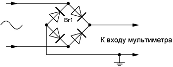
1.1.1. First, let's check the linearity of the frequency response of the sound card. There are a large number of programs that automatically measure the frequency response in the range of 20-20000 Hz (when the headphone output is connected to the microphone input of the sound card). But here I will describe a manual method for measuring the frequency response in the range of 10-500Hz (only this range is important for measuring the Til Small parameters of a low-frequency radiator). If an AC voltmeter with the ability to measure voltage of the order of 0.1 mV is not at hand, do not worry, you can use a regular inexpensive multimeter (Tester). Typically, such multimeters measure AC voltage with an accuracy of 0.1V and DC voltage with an accuracy of 0.1 mV. To measure an alternating voltage of the order of several mV, you just need to put a diode bridge in front of the multimeter input and measure direct voltage in the voltmeter mode in the range up to 200mV.
First, connect a voltmeter to the headphone output (Either to the right or to the left channel).

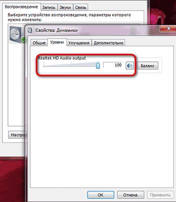
Turn off all sound effects and equalizers, open the speaker properties and set the volume level to 100%.
Open the program, press “Options”, in “Tone Interval” select “Frequency”, and set the step to 1Hz.

Close "Options", set the volume level to 100%, set the initial frequency to 10Hz and press "Play". With the “+” button, we begin smoothly, in 1 Hz steps, to increase the generator frequency to 500 Hz.

At the same time, we look at the voltage value on the voltmeter. If the maximum amplitude difference is within 2dB (1.259 times), then such a sound card is suitable for measuring speaker parameters. For me, for example, the maximum value was 624mV, and the minimum value was 568mV, 624/568 = 1.09859 (0.4dB), which is quite acceptable.
1.1.2. Let's move on to the long-awaited Thiel-Small parameters. The minimum parameters by which you can calculate and design acoustic design (in this case, a subwoofer) is:
- Resonance frequency (Fs),
- Total electromechanical quality factor (Qts),
- Equivalent volume (Vas).
For a more professional calculation, even more parameters are needed, such as mechanical quality factor (Qms), electrical quality factor (Qes), sensitivity (SPL), etc.
1.1.2.1. Determining the resonant frequency (Fs) of a loudspeaker.
We collect such a scheme.


The speaker should be in free space as far as possible from the walls, floor and ceiling (I hung it from a chandelier). We open the NCH Tone Generator program again, insist on the volume as described above, set the initial frequency to 10Hz and begin to gradually increase the frequency in 1Hz steps. At the same time, we again look at the value of the voltmeter, which will first increase, reach the maximum point (Umax) at the natural resonance frequency (Fs), and begin to decrease to the minimum point (Umin). With a further increase in frequency, the voltage will gradually increase. The graph of the dependence of voltage (active resistance of the speaker) on the frequency of the signal looks like this.

The frequency at which the voltmeter value is maximum is the approximate resonant frequency (at a step of 1 Hz). To determine the exact resonant frequency, it is necessary in the region of the approximate resonant frequency to change the frequency in steps no longer by 1 Hz, but by 0.05 Hz (accuracy 0.05 Hz). We write down the resonant frequency (Fs), the minimum value of the voltmeter (Umin), the value of the voltmeter at the resonant frequency (Umax) (in the future they will be useful for calculating the following parameters).
1.1.2.2.
Determination of the total electromechanical quality factor (Qts) of a loudspeaker.
Find UF1,F2 using the following formula.
![]()
By changing the frequency, we achieve the values of the voltmeter corresponding to the voltage UF1, F2. There will be two frequencies. One is below the resonant frequency (F1), the other is above (F2).

You can check the correctness of the calculations with this formula.

If the difference between Fs' and Fs does not exceed 1 Hz, then you can safely continue measurements. If not, then you need to do everything first. We find the mechanical quality factor (Qms) using this formula.

The electrical quality factor (Qes) is found using this formula.

Finally, we determine the total electromechanical quality factor (Qts) using this formula.

1.1.2.3. Determine the equivalent volume (Vas) of a loudspeaker.
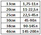
To determine the exact equivalent volume, we need a prefabricated, durable, sealed bass reflex box with a hole for our speaker.

The volume of the box depends on the diameter of the speaker, and is selected according to this table.
We fix the speaker to the box and connect it to the circuit described above (Fig. 9). Again, open the NCH Tone Generator program, set the initial frequency to 10Hz and use the “+” button to start smoothly, in 1Hz steps, to increase the generator frequency to 500Hz. At the same time, we look at the value of the voltmeter, which again begins to increase to the frequency FL, then decrease, reaching the minimum point at the frequency of the phase inverter (Fb), increase again and reach the maximum point at the frequency FH, then decrease and slowly increase again. The graph of the dependence of voltage on the frequency of the signal has the form of a two-humped camel.


And finally, we find the equivalent volume (Vas) using this formula (where Vb is the volume of the box with the phase inverter).

We repeat all our measurements 3-5 times and take the arithmetic mean of all parameters. For example, if we got the Fs values, respectively, 30.45Hz 30.75Hz 30.55Hz 30.6Hz 30.8Hz, then we take (30.45+30.75+30.55+30.6+30.8)/5= 30.63Hz.
As a result of all my measurements, I received the following parameters for my speaker:
- Fs=30.75Hz
- Qts=0.365
- Vas=112.9≈113 L
1.2. Modeling and calculation of the subwoofer case (box) using the JBL Speakershop program.
There are several options for acoustic design, of which the following options are most common.
- Vented box-box with phase inverter,
- Band-pass 4th, 6th and 8th order,
- Passive radiator - a box with a passive radiator,
- Closed box - a closed box.

The type of acoustic design is selected based on the Thiel-Small parameters of the loudspeaker. If Fs/Qts<50, то такой громкоговоритель можно использовать исключительно в закрытом оформлении, если Fs/Qts>100, then exclusively in Vented box or Band-pass or Closed box. If 50
First, download and install the program. This program is written for Windows XP and does not work on Windows 7. To make the program work on Windows 7, you need to download and install the Windows Virtual PC-XP Mode virtual machine (you can download it from the official Microsoft website), and run the installation of JBL Speakershop through it. You also need to open JBL Speakershop through a virtual machine. After opening the program, we see this interface.

We press “Loudspeaker” and select “Parameters--minimum”, in the open window we write, respectively, the value of the resonant frequency (Fs), the value of the equivalent volume (Vas), the value of the total electromechanical quality factor (Qts) and press “Accept”.

At the same time, the program will offer two optimal (with the most even frequency response) options, one in a closed design (Closed box), the other in a Vented box (box with a phase inverter). Press “plot” (both in the Vented box and in the Closed box) and look at the frequency response graph. We choose the design, the frequency response of which is most suitable for our requirements.

In my case, this is the Vented box, because at low frequencies (20-50Hz), the Closed box has a much larger amplitude drop than the Vented box (Figure above).
If the volume of the box suits you optimally, then you can build a box with such a volume and enjoy the sound of the subwoofer. If not (with too large volumes), then you need to set your own volume (the closer to the optimal volume, the better) and calculate the optimal tuning frequency of the phase inverter.

To do this, in the Vented box area, click “Custom”, in the window that opens, write your volume of the box, click “Optimum Fb” (in this case, the program will calculate the optimal tuning frequency of the phase inverter, at which the frequency response of the acoustic design will be the most linear) and then “Accept”.

Press “Box” and select “Vent…”, in the window that opens, in the “Custom” area, write the diameter of the pipe (Dv), which we will use as a phase inverter. If we use two phase inverters, then we put a dot on “Area” and write the total cross-sectional area of \u200b\u200bthe pipes.


Press “Accept” and in the “Custom” area on the line Lv the length of the phase inverter pipe will appear. Now that we know the internal volume of the box, the diameter and length of the phase inverter pipe, we can safely proceed to designing acoustic design, but if you really want to know the optimal aspect ratio of the box, you can press “Box”, select “Dimensions…”.

1.3. Designing the case (box) of the subwoofer
To obtain high-quality sound, it is necessary not only to correctly calculate, but also carefully manufacture the acoustic design case. After determining the internal volume of the box, the length and diameter of the phase inverter pipe, you can safely proceed to the manufacture of the subwoofer case. The material of the box must be sufficiently strong and rigid. The most suitable material for high power acoustic enclosures is 20 mm MDF. The walls of the box are attached to each other with self-tapping screws, and the gaps between them are smeared with sealant or silicone. After the box is made, holes are made for the handles, and the outer surface is finished. All irregularities are leveled with putty or epoxy (I add a little PVA glue to the putty, which prevents cracks from appearing over time and reduces the level of vibrations). After the putty dries, the surfaces must be sanded until perfectly smooth walls are obtained. The finished box can be either painted or covered with a self-adhesive decorative film, or simply glued on with a thick fabric. From the inside, a sound-absorbing material consisting of cotton wool and gauze is glued to the walls of the box (in my case, I glued the batting). As a phase inverter, you can use a plastic sewer pipe or a paper rod from different rolls, as well as a ready-made phase inverter that can be bought at almost any music store.
The housing of the active subwoofer consists of two compartments. The loudspeaker itself is located in the first compartment, and the entire electrical part (signal conditioner, amplifier, power supply ......) is located in the second. In my case, I placed the adder unit and the filter unit in a separate compartment from the power amplifier unit, power supply unit and cooling unit. From the inside, I glued foil to the walls of the compartment of the adder unit and the filter unit, which I connected to ground (GND). The foil prevents external fields and reduces noise levels.


If you use my printed circuit boards, then these compartments should have the following dimensions.


2. The electrical part of the active subwoofer
Let's move on to the electrical part of the active subwoofer. The general scheme and principle of operation of the device is represented by this scheme.
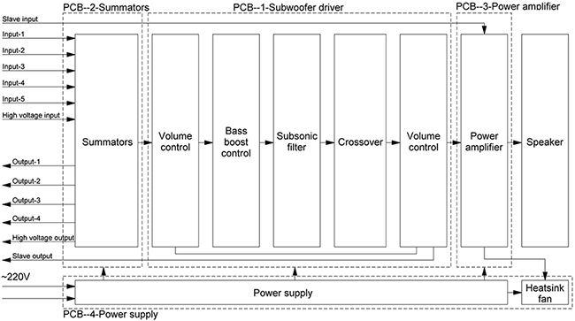
The device consists of four blocks assembled on separate printed circuit boards.
- Adder block (Summators),
- Filter unit (Subwoofer driver),
- Power amplifier block,
- Power supply (Power supply) and cooling unit (Heatsink fun).
First, the audio signal enters the Summators block, where the signals of the right and left channels are summed. Then it enters the filter unit (Subwoofer driver), where the subwoofer signal is formed, which includes a volume control, subsonic filter (low-pass filter), bass booster (volume increase at a certain frequency) and Crossover (low-pass filter). After formation, the signal enters the power amplifier unit (Power amplifier), and then to the loudspeaker.
We will discuss these blocks separately.
2.1. Block of adders (Summators)
2.1.1.Scheme
First, consider the adder circuit shown in the figure below.

The audio signal from external devices (computer, CD player……..) goes to the adder block, which has 6 stereo inputs. 5 of them are ordinary line inputs, differing from each other only in the type of connector. And the sixth is a high-voltage input, to which you can connect the speaker output (for example, a music center or car radio that do not have a line output). Each input has a separate op-amp combiner that shifts the right and left channel signals, which prevents the sound signal from one external device from being transmitted to another, while making it possible to connect several external devices to the subwoofer at the same time. And there are also outputs (5 outputs, the 6th one simply did not fit on the board, and therefore did not install), which make it possible to apply the same signal that enters the subwoofer to the input of a broadband stereo system. This is very convenient when the sound source has only one output.


2.1.2.Components
TL074 (5 pcs.) were used as operational amplifiers. Resistors are rated for 0.25W or higher (resistance ratings are shown in the diagram). All electrolytic capacitors have a voltage rating of 25 volts or higher (capacitance ratings are shown in the diagram). As non-polar capacitors, you can use ceramic or film capacitors (film is better), but if you really want to, you can put special audio capacitors (capacitors designed for use in high-quality audio systems). Chokes in the power supply circuit of operational amplifiers are designed to suppress the “noise” coming from the power supply. Coils L1-L4 contain 20 turns wound with copper wire with a diameter of 0.7mm, on the core of a gel pen (3mm). RCA, 3.5mm audio jack, 6.35mm audio jack, XLR, WP-8 connectors are also used.

2.1.3.Printed circuit board


The printed circuit board is made according to . After soldering the parts, the printed circuit board should be coated to avoid oxidation of the copper.
2.1.4. Photo of the finished adder block


The adder unit is powered by a bipolar ±12V power supply. The input impedance is 33kΩ.
2.2 Filter block (Subwoofer driver)
2.2.1.Scheme
Consider the subwoofer driver circuit shown in the figure below.

The summed signal from the adder block enters the filter block, which consists of the following parts:
- Volume control (volume regulator),
- Infra low pass filter (subsonic filter),
- Bass amplifier of a certain frequency (bass booster),
- Low pass filter (crossover).
Volume control takes place at two levels. The first is when the signal enters the filter block, which reduces the level of the own “noise” of the adder block, the second when the signal leaves the filter block, which reduces the level of the own “noise” of the filter block. The volume is adjusted using a variable resistor VR3. After the first level of volume control, the signal enters the so-called “bass booster”, which is a device that increases the amplitude of signals of a certain frequency. That is, if the bass booster tuning frequency is inserted, for example, at 44Hz, and the gain level is at 14dB, then the frequency response looks like this ( Row1).

Row2- tuning frequency=44Hz, gain level=9dB,
Row3- tuning frequency=44Hz, gain level=2dB,
Row4- tuning frequency=33Hz, gain level=3dB,
Row5- tuning frequency=61Hz, gain level=6dB.
The tuning frequency of the bass booster is inserted using a variable resistor VR5 (within 25 ... 125Hz), and the gain level with a resistor VR4 (within 0 ... + 14dB). After the bass booster, the signal enters the subsonic filter, which is a filter that cuts off unwanted, ultra-low signals that are no longer audible to humans, but can severely overload the amplifier, thereby reducing the actual output power of the system. The cutoff frequency of the filter is adjusted using a variable resistor VR2 within 10…80Hz. If, for example, the cutoff frequency is inserted at 25Hz, then the frequency response has the following form.

After the infra-low pass filter, the signal enters the low-pass filter (crossover), which cuts off the upper, unnecessary for the subwoofer (mid + high) frequencies. The cutoff frequency is adjusted using a variable resistor VR1 within 30 ... 250 Hz. The slope of the attenuation is 12 dB / octave. The frequency response has this form (at a cutoff frequency of 70 Hz).

2.2.2.Components
TL074 (2pcs), TL072 (1pc) and NE5532 (1pc) were used as operational amplifiers. Resistors are rated for 0.25W or higher (resistance ratings are shown in the diagram). All electrolytic capacitors have a voltage rating of 25 volts or higher (capacitance ratings are shown in the diagram). As non-polar capacitors, ceramic or film capacitors (preferably film ones) can be used. Chokes in the power supply circuit of operational amplifiers are designed to suppress the “noise” coming from the power supply. Three double (50kOhm-2pcs, 20kOhm-1pcs) and two quad variable (50kOhm-6pcs) resistors are also used. Two dual resistors can be used as quad variable resistors.
2.2.3.Printed circuit board

PCB files in *.lay and *.pdf format can be downloaded at the end of the article.
2.2.4. Photo of the finished filter unit


The filter unit is powered by a bipolar ±12V power supply.
2.3. Block power amplifier (Power amplifier).
2.3.1.Scheme
An Anthony Holton amplifier with field-effect transistors in the output stage is used as a power amplifier. There are a lot of articles describing the principle of operation, assembly and tuning of the amplifier on the Internet. Therefore, I will limit myself to embedding the schematic and my version of the PCB.

2.3.2.Printed circuit board
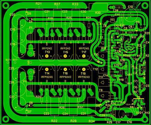


PCB files in *.lay and *.pdf format can be downloaded at the end of the article. The power amplifier unit is powered by a bipolar power supply with a voltage of ± 50 ... 63V. The output power of the amplifier depends on the supply voltage and the number of pairs of field-effect transistors (IRFP240 + IRFP9240) in the output stage.
2.4. Power supply and cooling unit (Power supply)
2.4.1.Scheme

2.4.2.Components
As a power transformer, you can use both a ready-made and a home-made transformer with a power of approximately 200W. The voltages of the secondary windings are shown in the diagram.


The diode bridge Br2 is designed for a current of 25A. Capacitors C1 ... C12, C29 ... C31 must have a rated voltage of 25V. Capacitors C13…C28 must have a nominal voltage of 63V (when the supply voltage is below 60V), or 100V (when the supply voltage is above 60V). As non-polar capacitors, it is better to use film capacitors. All resistors are rated at 0.25W. The R5 thermistor is smeared with thermal paste and attached to the amplifier heatsink. The operating voltage of the fan is 12V.
2.4.3.Printed circuit board

PCB files in *.lay and *.pdf format can be downloaded at the end of the article.
3. The final stage of subwoofer assembly


List of radio elements
| Designation | Type of | Denomination | Quantity | Note | Score | My notepad | |
|---|---|---|---|---|---|---|---|
| U1-U5 | Operational amplifier | TL074 | 5 | To notepad | |||
| C1-C4, C15, C16, C25-C27, C29, C39-C42 | 10 uF | 14 | To notepad | ||||
| C5-C10, C23, C24, C28, C30, C35-C38 | Capacitor | 33 pF | 14 | To notepad | |||
| C11-C14, C19-C22, C31-C34 | Capacitor | 0.1uF | 12 | To notepad | |||
| C17, C18 | electrolytic capacitor | 470uF | 2 | To notepad | |||
| R1, R2 | Resistor | 390 ohm | 2 | To notepad | |||
| R3, R12 | Resistor | 15 kOhm | 2 | To notepad | |||
| R4, R16-R18 | Resistor | 20 kOhm | 4 | To notepad | |||
| R5, R13-R15 | Resistor | 13 kOhm | 4 | To notepad | |||
| R6, R10, R23, R24, R31, R33, R40, R41, R46, R47 | Resistor | 68 kOhm | 10 | To notepad | |||
| R7, R11, R21, R22, R32, R34, R37, R38, R45, R48 | Resistor | 22 kOhm | 10 | To notepad | |||
| R8, R9, R25, R26, R29, R30, R39, R42, R49, R50 | Resistor | 10 kOhm | 10 | To notepad | |||
| R19, R20, R27, R28, R35, R36, R43, R44 | Resistor | 22 ohm | 8 | To notepad | |||
| L1-L4 | Inductor | 20x3mm | 4 | 20 turns, wire 0.7mm, rim 3mm | To notepad | ||
| L5-L13 | Inductor | 100 mH | 10 | To notepad | |||
| Filter block | |||||||
| U1 | Operational amplifier | TL072 | 1 | To notepad | |||
| U2, U4 | Operational amplifier | TL074 | 2 | To notepad | |||
| U3 | Operational amplifier | NE5532 | 1 | To notepad | |||
| C1-C5, C7-C10, C15-C17, C20, C23 | Capacitor | 0.1uF | 14 | To notepad | |||
| C6 | Capacitor | 15 nF | 1 | To notepad | |||
| C11-C14 | Capacitor | 0.33uF | 4 | To notepad | |||
| C21, C22 | Capacitor | 82 nF | 2 | To notepad | |||
| VR1-VR3, VR5 | Variable resistor | 50 kOhm | 4 | To notepad | |||
| VR4 | Variable resistor | 20 kOhm | 1 | To notepad | |||
| R1, R3, R4, R6 | Resistor | 6.8 kOhm | 4 | To notepad | |||
| R2, R10, R11, R13, R14 | Resistor | 4.7 kOhm | 5 | To notepad | |||
| R5, R8 | Resistor | 10 kOhm | 2 | To notepad | |||
| R7, R9 | Resistor | 18 kOhm | 2 | To notepad | |||
| R12, R15-R17, R20, R22, R26, R27 | Resistor | 2 kOhm | 8 | To notepad | |||
| R18, R25 | Resistor | 3.6 kOhm | 2 | To notepad | |||
| R19, R21 | Resistor | 1.5 kOhm | 2 | To notepad | |||
| R23, R24, R30, R31, R33 | Resistor | 20 kOhm | 5 | To notepad | |||
| R28 | Resistor | 13 kOhm | 1 | To notepad | |||
| R29 | Resistor | 36 kOhm | 1 | To notepad | |||
| R32 | Resistor | 75 kOhm | 1 | To notepad | |||
| R34, R35 | Resistor | 15 kOhm | 2 | To notepad | |||
| L1-L8 | Inductor | 100 mH | 1 | To notepad | |||
| Power amplifier block | |||||||
| T1-T4 | bipolar transistor | 2N5551 | 4 | To notepad | |||
| T5, T9, T11, T12 | bipolar transistor | MJE340 | 4 | To notepad | |||
| T7, T8, T10 | bipolar transistor | MJE350 | 3 | To notepad | |||
| T13, T15, T17 | MOSFET transistor | IRFP240 | 3 | To notepad | |||
| T14, T16, T18 | MOSFET transistor | IRFP9240 | 3 | To notepad | |||
| D1, D2, D5, D7 | rectifier diode | 1N4148 | 4 | To notepad | |||
| D3, D4, D6 | zener diode | 1N4742 | 3 | To notepad | |||
| D8, D9 | rectifier diode | 1N4007 | 2 | ||||