Field effect transistor irf 10 amperes. Powerful imported field effect transistors
In technology and amateur radio practice, field-effect transistors are often used. Such devices differ from conventional, bipolar, transistors in that they control the output signal by a control electric field. Insulated gate field-effect transistors are especially commonly used.
The English designation for such transistors is MOSFET, which means "field-controlled metal oxide semiconductor transistor." In the domestic literature, these devices are often called MOS or MOS transistors. Depending on the manufacturing technology, such transistors can be n- or p-channel.
An n-channel transistor consists of a silicon substrate with p-conductivity, n-regions obtained by adding impurities to the substrate, a dielectric that insulates the gate from the channel located between the n-regions. The pins (source and drain) are connected to the n-regions. Under the action of the power supply, current can flow from the source to the drain through the transistor. The magnitude of this current is controlled by the isolated gate of the device.
When working with field-effect transistors, it is necessary to take into account their sensitivity to the effects of an electric field. Therefore, they must be stored with the leads shorted with foil, and before soldering, the leads must be short-circuited with a wire. It is necessary to solder the field-effect transistors using a soldering station, which provides protection against static electricity.
Before you start checking the health of the field-effect transistor, you need to determine its pinout. Often on an imported device, labels are applied that determine the corresponding terminals of the transistor.
The letter G denotes the shutter of the device, the letter S denotes the source, and the letter D denotes the drain.
If there is no pinout on the device, you must see it in the documentation for this device.
Scheme for checking an n-channel type field-effect transistor with a multimeter
Before checking the serviceability of the field-effect transistor, it must be borne in mind that in modern radio components of the MOSFET type there is an additional diode between the drain and the source. This element is usually present on the device diagram. Its polarity depends on the type of transistor.
 The general rules are to begin the procedure by determining the operability of the measuring device itself. After making sure that it works flawlessly, proceed to further measurements.
Conclusions:
- Field-effect transistors of the MOSFET type are widely used in technology and amateur radio practice.
- Checking the performance of such transistors can be carried out using a multimeter, following a specific technique.
- Checking a p-channel field-effect transistor with a multimeter is carried out in the same way as an n-channel transistor, except that the polarity of the multimeter wires should be reversed.
Video on how to check a field-effect transistor
A transistor is a semiconductor electronic component. We refer it to the active elements of the circuit, since it allows converting electrical signals (nonlinearly).
Field or MOSFET(Metal-Oxide Semiconductor Field-Effect Transistor) - a field-effect transistor with a metal-oxide-semiconductor structure. Therefore, it is often referred to simply as a MOSFET.
Transistors produced using this technology consist of three layers:
- The first layer is a wafer cut from a homogeneous silicon crystal or from silicon doped with germanium.
- The second layer in order is the deposition of a very thin dielectric (insulator) layer of silicon dioxide or metal oxide (aluminum or zirconium oxides). The thickness of this layer is, depending on the execution technology, about 10 nm, and in the best case, the thickness of this layer can be about 1.2 nm. For comparison: 5 silicon atoms located close to each other just make up a thickness close to 1.2 nm.
- The third layer is a highly conductive metal. Most often, gold is used for this purpose.
The design of such a transistor is schematically shown below:
It should be noted that field-effect transistors are of two types: N-type and P-type, much the same as in the case of bipolar transistors, which are produced in PNP and NPN versions.
Among the field-effect transistors, the N-type is much more common. In addition, there are field-effect transistors:
- with a depleted channel, that is, those that pass a weak current through themselves in the absence of a voltage at the gate, and in order to completely block it, it is necessary to apply a reverse bias of a couple of volts to the gate;
- with an enriched channel - this is a type of field-effect transistors that, in the absence of voltage at the gate, do not conduct current, but conduct it only when the voltage applied to the gate exceeds the source voltage.

The big advantage of field-effect transistors is that they are voltage controlled, as opposed to bipolar transistors, which are current controlled.
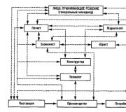
It is easier to understand the principle of their operation of a field-effect transistor using the example of a hydraulic crane.

To control the high pressure fluid flow in a large pipe requires little effort to open or close the valve. In other words, with a small amount of work, we get a big effect. The little force we put on the handle of the faucet controls the much more force of the water, which presses on the valve.
Thanks to this property of field-effect transistors, we can control currents and voltages that are much higher than those that are given to us, for example, by a microcontroller.
As noted earlier, a conventional MOSFET generally does not conduct current from source to drain. To translate such a transistor into a conduction state, it is necessary to apply a voltage between the source and the gate as shown in the figure below.

The following figure shows the current-voltage characteristic of the IRF540 transistor.

The graph shows that the transistor begins to conduct when the voltage between the gate and the source approaches 4V. However, it takes almost 7 volts to fully open. This is much more than the output of the microcontroller.
In some cases, a current of 15 mA and a voltage of 5V may be sufficient. But what if it's too little? There are two ways out.
- You can use special MOS transistors with reduced gate-source voltage, for example, BUZ10L.
- Alternatively, you can use an additional amplifier to increase the control voltage.
Regardless of the application, each field-effect transistor has several key parameters, namely:
- Allowable drain-source voltage: UDSmax
- Maximum drain current: IDmax
- Opening threshold voltage: UGSth
- Channel on-resistance: RDSon
In many cases, RDSon is the key parameter, since it indirectly indicates to us the loss of power, which is highly undesirable.
For example, let's take a transistor in a TO-220 package with a resistance RDSon = 0.05 Ohm and a current of 4A flowing through this transistor.

Let's calculate the power loss:
- UDS = 0.05Ω x 4A = 0.2V
- P = 0.2V x 4A = 0.8W
The power loss that the transistor in the TO-220 case is capable of dissipating is slightly more than 1 W, so in this case you can do without a radiator. However, even for a current of 10A, the losses will amount to 5W, so you can't do without a radiator.
Therefore, the smaller the RDSon, the better. Therefore, when choosing a MOSFET for a particular application, this parameter should always be taken into account.
In practice, with an increase in the allowable voltage UDSmax, the source-drain resistance increases. For this reason, you should not choose transistors with a larger than required UDSmax.
MOP (bourgeois MOSFET) stands for Metal-Oxide-Semiconductor from this abbreviation, the structure of this transistor becomes clear.
If on the fingers, then there is a semiconductor channel in it, which serves as a kind of one plate of a capacitor and the second plate is a metal electrode located through a thin layer of silicon oxide, which is a dielectric. When a voltage is applied to the gate, this capacitor is charged, and the electric field of the gate pulls charges to the channel, as a result of which mobile charges appear in the channel that can form an electric current and the drain-to-source resistance drops sharply. The higher the voltage, the more charges and the lower the resistance, as a result, the resistance can drop to scanty values - hundredths of an ohm, and if you raise the voltage further, the oxide layer will break down and the khan transistor.
The advantage of such a transistor, in comparison with a bipolar one, is obvious - voltage must be applied to the gate, but since there is a dielectric, the current will be zero, which means the required the power to control this transistor will be scanty, in fact, it consumes only at the moment of switching, when the capacitor is charged and discharged.
The disadvantage stems from its capacitive property - the presence of a capacitance at the gate requires a large charging current when opened. In theory, equal to infinity at infinitesimal intervals of time. And if the current is limited by a resistor, then the capacitor will charge slowly - you can't get away from the RC circuit time constant.
MOS Transistors are P and N channel. Their principle is the same, the only difference is in the polarity of the current carriers in the channel. Accordingly, in a different direction of the control voltage and inclusion in the circuit. Very often, transistors are made in the form of complementary pairs. That is, there are two models with completely identical characteristics, but one of them is N, and the other is P channel. Their marking, as a rule, differs by one digit.
 |
I have the most popular MNP transistors are IRF630(n channel) and IRF9630(p channel) at one time I mixed them with a dozen and a half of each type. Possessing a not very large body TO-92 this transistor can famously pull through itself up to 9A. Its open resistance is only 0.35 Ohm.
However, this is a rather old transistor, now there are things more abruptly, for example IRF7314, capable of pulling the same 9A, but at the same time it fits into the SO8 case - the size of a notebook cell.
One of the problems of docking MOSFET transistor and microcontroller (or digital circuit) is that in order to fully open until full saturation, this transistor must be rolled into the gate rather more voltage. Usually this is about 10 volts, and the MK can give a maximum of 5.
There are three options:
 But in general, it is still more correct to install the driver, because in addition to the basic functions of generating control signals, as an additional bauble, it also provides current protection, protection against breakdown, overvoltage, optimizes the opening speed to the maximum, in general, it does not eat its current in vain.
 The choice of a transistor is also not very difficult, especially if you do not bother with limiting modes. First of all, you should be worried about the value of the drain current - I Drain or I D choose a transistor for the maximum current for your load, better with a margin of 10 percent. The next important parameter for you is V GS- the saturation voltage of the Source-Gate, or, more simply, the control voltage. Sometimes they write it, but more often they have to look out of the charts. Looking for a graph of the output characteristic Dependency I D from V DS at different values V GS... And you figure out what kind of regime you will have.
For example, you need to power the engine at 12 volts, with a current of 8A. The driver got stuck and you only have a 5 volt control signal. The first thing that came to mind after this article is the IRF630. Suitable for current with a margin of 9A against the required 8. But let's look at the output characteristic:
If you are going to drive a PWM to this key, then you need to inquire about the opening and closing times of the transistor, choose the highest one and, relative to the time, calculate the maximum frequency that it is capable of. This value is called Switch delay or t on,t off, in general, something like this. Well, the frequency is 1 / t. Also, it will not be superfluous to look at the shutter capacity. C iss based on it, as well as the limiting resistor in the gate circuit, you can calculate the charge time constant of the gate RC circuit and estimate the speed. If the time constant is greater than the PWM period, then the transistor will not open / close, but will hang in some intermediate state, since the voltage at its gate will be integrated by this RC circuit into a constant voltage.
When handling these transistors, consider the fact that they are afraid of static electricity not just strongly, but VERY STRONG... It is more than realistic to pierce the shutter with a static charge. So how I bought it, immediately in foil and don't get it out until you solder it. We grounded ourselves behind the battery and put on a foil hat :).

Technological capabilities and advances in the development of powerful field-effect transistors have led to the fact that at present it is not difficult to acquire them at an affordable price.
In this regard, the interest of radio amateurs in the use of such MOSFET transistors in their electronic homemade products and projects has increased.
It is worth noting the fact that MOSFETs differ significantly from their bipolar counterparts, both in terms of parameters and their device.
It's time to get acquainted with the device and parameters of powerful MOSFET transistors, so that, if necessary, more consciously choose an analog for a particular instance, and also be able to understand the essence of certain values indicated in the datasheet.
What is a HEXFET transistor?
Within the FET family, there is a separate group of powerful semiconductor devices called HEXFETs. Their principle of operation is based on a very original technical solution. Their structure is several thousand MOS cells connected in parallel.
Cellular structures form a hexagon. Due to the hexagonal or otherwise hexagonal structure, this type of power MOS transistors is called HEXFET. The first three letters of this abbreviation are taken from the English word hex agonal- "hexagonal".
Under the multiple magnification, the crystal of a powerful HEXFET transistor looks like this.

As you can see, it has a hexagonal structure.
It turns out that a powerful MOSFET is, in fact, a kind of super-microcircuit, in which thousands of individual simple field-effect transistors are combined. Together, they create one powerful transistor that can pass a large current through itself and at the same time practically do not provide significant resistance.
Due to the special structure and manufacturing technology of the HEXFET, the resistance of their channel R DS (on) managed to significantly reduce. This made it possible to solve the problem of switching currents of several tens of amperes at voltages up to 1000 volts.
Here is just a small area of application for high-power HEXFET transistors:
Power supply switching diagrams.
Charging device.
Electric motor control systems.
Low frequency amplifiers.
Despite the fact that mosfets made using the HEXFET technology (parallel channels) have a relatively low open-channel resistance, their scope is limited, and they are mainly used in high-frequency high-current circuits. In high-voltage power electronics, IGBT-based circuits are sometimes preferred.

A schematic diagram of a MOSFET transistor (N-channel MOSFET).

Like bipolar transistors, field-effect structures can be forward conduction or reverse. That is, with a P-channel or N-channel. Conclusions are indicated as follows:
D-drain (drain);
S-source
G-gate (shutter).
You can find out how the field-effect transistors of different types are indicated on the circuit diagrams on this page.
The main parameters of field-effect transistors.
The entire set of MOSFET parameters may be required only by developers of complex electronic equipment and, as a rule, is not indicated in the datasheet (reference sheet). It is enough to know the basic parameters:
V DSS(Drain-to-Source Voltage) - voltage between drain and source. This is usually the supply voltage of your circuit. When choosing a transistor, you should always remember about a 20% margin.
I D(Continuous Drain Current) - drain current or continuous drain current. Always indicated when the gate-source voltage is constant (eg V GS = 10V). The datasheet, as a rule, indicates the maximum possible current.
R DS (on)(Static Drain-to-Source On-Resistance) - drain-to-source resistance of an open channel. With an increase in the crystal temperature, the resistance of the open channel increases. This can be easily seen on the graph taken from the datasheet of one of the powerful HEXFET transistors. The lower the resistance of the open channel (R DS (on)), the better the mosfet. It heats up less.

P D(Power Dissipation) - The power of the transistor in watts. In another way, this parameter is also called the dissipation power. In the datasheet for a specific product, the value of this parameter is indicated for a specific temperature of the crystal.
V GS(Gate-to-Source Voltage) - gate-source saturation voltage. This voltage, when exceeded, does not increase the current through the channel. Basically, this is the maximum voltage between gate and source.
V GS (th)(Gate Threshold Voltage) - the threshold voltage for turning on the transistor. This is the voltage at which the opening of the conducting channel occurs and it begins to pass current between the terminals of the source and drain. If a voltage less than V GS (th) is applied between the terminals of the gate and the source, then the transistor will be turned off.

The graph shows how the threshold voltage V GS (th) decreases with increasing crystal temperature of the transistor. At 175 0 C it is about 1 volt, and at 0 0 C it is about 2.4 volts. Therefore, the datasheet, as a rule, indicates the minimum ( min.) and maximum ( max.) threshold voltage.
 Let's consider the main parameters of a powerful field-effect HEXFET transistor using an example IRLZ44ZS by International Rectifier. Despite its impressive specs, it has a small footprint D 2 PAK for surface mounting. Let's look at the datasheet and evaluate the parameters of this product.
Drain-source voltage limit (V DSS): 55 Volts.
Maximum drain current (I D): 51 Amps.
Limit gate-source voltage (V GS): 16 Volts.
Open channel drain-source resistance (R DS (on)): 13.5 mΩ.
Maximum power (P D): 80 watts.
The open channel resistance of the IRLZ44ZS is only 13.5 milliohms (0.0135 ohms)!
Let's take a look at the "piece" from the table, where the maximum parameters are indicated.

It is clearly seen how with a constant gate voltage, but with an increase in temperature, the current decreases (from 51A (at t = 25 0 C) to 36A (at t = 100 0 C)). Power at a case temperature of 25 0 С is equal to 80 watts. Some parameters in the pulse mode are also indicated.
MOSFETs are fast, but they have one major drawback - a large gate capacity. In the documents, the input capacity of the shutter is indicated as C iss (Input Capacitance).
What does the shutter capacity affect? It largely influences certain properties of field-effect transistors. Since the input capacitance is large enough, and can reach tens of picofarads, the use of field-effect transistors in high-frequency circuits is limited.
Important features of MOSFET transistors.
It is very important when working with field-effect transistors, especially with an insulated gate, to remember that they are "deadly" afraid of static electricity... It is possible to solder them into the circuit only by shorting the leads together with a thin wire.
During storage, all the terminals of the MOSFET are best short-circuited using ordinary aluminum foil. This will reduce the risk of static electricity breakdown of the gate. When mounting it on a PCB, it is better to use a soldering station rather than a regular electric soldering iron.
The fact is that an ordinary electric soldering iron has no protection against static electricity and is not "decoupled" from the mains through a transformer. On its copper sting, there are always electromagnetic "pickups" from the mains.
Any surge in the mains voltage can damage the item being soldered. Therefore, by soldering the field-effect transistor into the circuit with an electric soldering iron, we risk damaging the MOSFET.
POWERFUL IMPORTED FIELD TRANSISTORS
| Brand | Voltage, V | Junction resistance, Ohm | Drain current, A | Power, W | Frame | ||
| 1 | 2 | 3 | 4 | 5 | 6 | ||
| STH60N0SFI | 50 | 0,023 | 40,0 | 65 | ISOWATT218 | ||
| STVHD90FI | 50 | 0,023 | 30,0 | 40 | ISOWATT220 | ||
| STVHD90 | 50 | 0,023 | 52,0 | 125 | TO-220 | ||
| STH60N05 | 50 | 0,023 | 60,0 | 150 | TO-218 | ||
| IRFZ40 | 50 | 0,028 | 35.0 | 125 | TO-220 | ||
| BUZ15 | 50 | 0.03 | 45,0 | 125 | TO-3 | ||
| SGSP592 | 50 | 0,033 | 40,0 | 150 | TO-3 | ||
| SGSP492 | 50 | 0.033 | 40,0 | 150 | TO-218 | ||
| IRFZ42FI | 50 | 0,035 | 24,0 | 40 | ISOWATT220 | ||
| IRFZ42 | 50 | 0,035 | 35,0 | 125 | TO-220 | ||
| BUZ11FI | 50 | 0,04 | 20,0 | 35 | ISOWATT220 | ||
| BUZ11 | 50 | 0,04 | 30,0 | 75 | TO-220 | ||
| BUZ14 | 50 | 0,04 | 39,0 | 125 | TO-3 | ||
| BUZ11A | 50 | 0,06 | 25,0 | 75 | TO-220 | ||
| SGSP382 | 50 | 0.06 | 28,0 | 100 | TO-220 | ||
| SGSP482 | 50 | 0.06 | 30.0 | 125 | TO-218 | ||
| BUZ10 | 50 | 0.08 | 20.0 | 70 | TO-220 | ||
| BUZ71FI | 50 | 0,10 | 12,0 | 30 | ISOWATT220 | ||
| IRF20FI | 50 | 0,10 | 12,5 | 30 | ISOWATT220 | ||
| BUZ71 | 50 | 6,10 | 14,0 | 40 | TO-220 | ||
| IRFZ20 | 50 | 0,10 | 15.0 | 40 | TO-220 | ||
| BUZ71AFI | 50 | 0,12 | 11,0 | 30 | ISOWATT220 | ||
| IRFZ22FI | 50 | 0,12 | 12,0 | 30 | ISOWATT220 | ||
| BUZ71A | 50 | 0,12 | 13,0 | 40 | TO-220 | ||
| IRFZ22 | 50 | 0,12 | 14,0 | 40 | TO-220 | ||
| BUZ10A | 50 | 0,12 | 17,0 | 75 | TO-220 | ||
| SGSP322 | 50 | 0,13 | 16,0 | 75 | TO-220 | ||
| SGSP358 | 50 | 0.30 | 7,0 | 50 | TO-220 | ||
| MTH40N06FI | 60 | 0,028 | 26,0 | 65 | ISOWATT218 | ||
| MTH40N06 | 60 | 0,028 | 40,0 | 150 | TO-218 | ||
| SGSP591 | 60 | 0,033 | 40,0 | 150 | TO-3 | ||
| SGSP491 | 60 | 0,033 | 40,0 | 150 | TO-218 | ||
| BUZ11S2FI | 60 | 0,04 | 20,0 | 35 | ISOWATT220 | ||
| BUZ11S2 | 60 | 0,04 | 30,0 | 75 | TO-220 | ||
| IRFP151FI | 60 | 0,055 | 26,0 | 65 | ISOWATT218 | ||
| IRF151 | 60 | 0.055 | 40,0 | 150 | TO-3 | ||
| IRFP151 | 60 | 0.055 | 40,0 | 150 | TO-218 | ||
| SGSP381 | 60 | 0,06 | 28,0 | 100 | TO-220 | ||
| SGSP481 | 60 | 0.06 | 30.0 | 125 | TO-218 | ||
| IRFP153FI | 60 | 0,08 | 21,0 | 65 | ISOWATT218 | ||
| IRF153 | 60 | 0,08 | 33,0 | 150 | TO-3 | ||
| IRFP153 | 60 | 0,08 | 34.0 | 150 | TO-218 | ||
| SGSP321 | 60 | 0,13 | 16,0 | 75 | TO-220 | ||
| MTP3055EFI | 60 | 0,15 | 10,0 | 30 | ISOWATT220 | ||
| МТР3055Е | 60 | 0,15 | 12.0 | 40 | TO-220 | ||
| IRF521FI | 80 | 0,27 | 7,0 | 30 | ISOWATT220 | ||
| IRF521 | 80 | 0.27 | 9,2 | 60 | TO-220 | ||
| IRF523FI | 80 | 036 | 6,0 | 30 | ISOWATT220 | ||
| IRF523 | 80 | 0.36 | 8,0 | 60 | TO-220 | ||
| SGSP472 | 80 | 0,05 | 35.0 | 150 | TO-218 | ||
| IRF541 | 80 | 0,077 | 15,0 | 40 | ISOWATT220 | ||
| IRF141 | 80 | 0.077 | 28,0 | 125 | TO-3 | ||
| IRF541 | 80 | 0.077 | 28,0 | 125 | TO-220 | ||
| IRF543F1 | 80 | 0,10 | 14,0 | 40 | SOWATT220 | ||
| SGSP362 | 80 | 0,10 | 22.0 | 100 | TO-220 | ||
| IRF143 | 80 | 0,10 | 25,0 | 125 | TO-3 | ||
| SGSP462 | 80 | 0.10 | 25,0 | 125 | TO-218 | ||
| IRF543 | 80 | 0,10 | 25.0 | 125 | O-220 | ||
| IRF531FI | 80 | 0.16 | 9,0 | 35 | SOWATT220 | ||
| IRF531 | 80 | 0.16 | 14,0 | 79 | O-220 | ||
| IRF533FI | 80 | 0,23 | 8,0 | 35 | ISOWATT220 | ||
| IRF533 | 80 | 0,23 | 12.0 | 79 | TO-220 | ||
| IRF511 | 80 | 0,54 | 5.6 | 43 | TO-220 | ||
| IRF513 | 80 | 0,74 | 4,9 | 43 | TO-220 | ||
| IRFP150FI | 100 | 0,055 | 26,0 | 65 | ISOWATT218 | ||
| IRF150 | 100 | 0,055 | 40,0 | 150 | TO-3 | ||
| IRFP150 | 100 | 0,055 | 40,0 | 150 | TO-218 | ||
| BUZ24 | 100 | 0,6 | 32,0 | 125 | TO-3 | ||
| IRF540FI | 100 | 0,077 | 15,0 | 40 | ISOWATT220 | ||
| IRF140 | 100 | 0,077 | 28,0 | 125 | TO-3 | ||
| IRF540 | 100 | 0,077 | 28,0 | 125 | TO-220 | ||
| SGSP471 | 100 | 0,075 | 30,0 | 150 | TO-218 | ||
| IRFP152FI | 100 | 0,08 | 21,0 | 65 | ISOWATT218 | ||
| IRF152 | 100 | 0,08 | 33,0 | 150 | TO-3 | ||
| IRFP152 | 100 | 0,08 | 34.0 | 150 | TO-218 | ||
| IRF542FI | 100 | 0,10 | 14,0 | 40 | ISOWATT220 | ||
| BUZ21 | 100 | 0,10 | 19.0 | 75 | TO-220 | ||
| BUZ25 | 100 | 0,10 | 19.0 | 78 | TO-3 | ||
| IRF142 | 100 | 0,10 | 25,0 | 125 | TO-3 | ||
| IRF542 | 100" | 0,10 | 25,0 | 125 | TO-220 | ||
| SGSP361 | 100 | 0,15 | 18,0 | 100 | TO-220 | ||
| SGSP461 | 100 | 0,15 | 20.0 | 125 | TO-218 | ||
| IRF530FI | 100 | 0,16 | 9,0 | 35 | ISOWATT220 | ||
| IRF530 | 100 | 0,16 | 14.0 | 79 | TO-220 | ||
| BUZ20 | 100 | 0,20 | 12.0 | 75 | TO-220 | ||
| IRF532FI | 100 | 0.23 | 8.0 | 35 | ISOWATT220 | ||
| IRF532 | 100 | 0,23 | 12,0 | 79 | TO-220 | ||
| BUZ72A | 100 | 0,25 | 9,0 | 40 | TO-220 | ||
| IRF520FI | 100 | 0.27 | 7,0 | 30 | ISOWATT220 | ||
| IRF520 | 100 | 0,27 | 9,2 | 60 | TO-220 | ||
| SGSP311 | 100 | 0,30 | 11.0 | 75 | TO-220 | ||
| IRF522FI | 100 | 0,36 | 6.0 | 30 | ISOWATT220 | ||
| IRF522 | 100 | 0,36 | 8,0 | 60 | TO-220 | ||
| IRF510 | 100 | 0,54 | 5,6 | 43 | TO-220 | ||
| SGSP351 | 100 | 0,60 | 6,0 | 50 | TO-220 | ||
| IRF512 | 100 | 0,74 | 4,9 | 43 | TO-220 | ||
| SGSP301 | 100 | 1,40 | 2,5 | 18 | TO-220 | ||
| IRF621FI | 160 | 0,80 | 4.0 | 30 | ISOWATT220 | ||
| IRF621 | 150 | 0,80 | 5,0 | 40 | TO-220 | ||
| IRF623FI | 150 | 1,20 | 3,5 | 30 | ISOWATT220 | ||
| IRF623 | 150 | 1.20 | 4.0 | 40 | TO-220 | ||
| STH33N20FI | 200 | 0.085 | 20.0 | 70 | ISOWATT220 | ||
| SGSP577 | 200 | 0,17 | 20,0 | 150 | TO-3 | ||
| SGSP477 | 200 | 0,17 | 20,0 | 150 | TO-218 | ||
| 8UZ34 | 200 | 0,20 | 19,0 | 150 | TO-3 | ||
| SGSP367 | 200 | 0,33 | 12,0 | 100 | TO-220 | ||
| BUZ32 | 200 | 0,40 | 9,5 | 75 | TO-220 | ||
| SGSP317 | 200 | 0,75 | 6,0 | 75 | TO-220 | ||
| IRF620FI | 200 | 0,80 | 4,0 | 30 | ISOWATT220 | ||
| IRF620 | 200 | 0,80 | 5,0 | 40 | TO220 | ||
| IRF622FI | 200 | 1.20 | 3,5 | 30 | ISOWATT220 | ||
| IRF622 | 200 | 1.20 | 4,0 | 40 | TO-220 | ||
| IRF741FI | 350 | 0.55 | 5,5 | 40 | ISOWATT220 | ||
| IRF741 | 350 | 0,55 | 10,0 | 125 | TO-220 | ||
| IRF743 | 350 | 0.80 | 8,3 | 125 | TO-220 | ||
| IRF731FI | 350 | 1,00 | 3,5 | 35 | ISOWATT220 | ||
| IRF731 | 350 | 1,00 | 5,5 | 75 | TO-220 | ||
| IRF733FI | 350 | 1,50 | 3,0 | 35 | ISOWATT220 | ||
| IRF733 | 350 | 1,50 | 4.5 | 75 | TO-220 | ||
| IRF721FI | 350 | 1,80 | 2.5 | 30 | ISOWATT220 | ||
| IRF721 | 350 | 1,80 | 3.3 | 50 | TO-220 | ||
| IRF723FI | 350 | 2,50 | 2,0 | 30 | ISOWATT220 | ||
| IRF723 | 350 | 2,50 | 2,8 | 50 | TO-220 | ||
| IRFP350FI | 400 | 0,30 | 10,0 | 70 | ISOWATT218 | ||
| IRF350 | 400 | 0,30 | 15,0 | 150 | TO-3 | ||
| IRFP350 | 400 | 0,30 | 16,0 | 180 | TO-218 | ||
| IRF740FI | 400 | 0,55 | 5,5 | 40 | ISOWATT220 | ||
| IRF740 | 400 | 0,55 | 10,0 | 125 | TO-220 | ||
| SGSP475 | 400 | 0,55 | 10,0 | 150 | TO-218 | ||
| IRF742FI | 400 | 0,80 | 4,5 | 40 | ISOWATT220 | ||
| IRF742 | 400 | 0,80 | 8,3 | 125 | TO-220 | ||
| IRF730FI | 400 | 1,00 | 3,5 | 35 | ISOWATT220 | ||
| BUZ60 | 400 | 1,00 | 5,5 | 75 | TO-220 | ||
| IRF730 | 400 | 1,00 | 5,5 | 75 | TO-220 | ||
| IRF732FI | 400 | 1,50 | 3,0 | 35 | ISOWATT220 | ||
| BUZ60B | 400 | 1,50 | 4,5 | 75 | TO-220 | ||
| IRF732 | 400 | 1,50 | 4,5 | 75 | TO-220 | ||
| IRF720FI | 400 | 1,80 | 2,5 | 30 | ISOWATT220 | ||
| BUZ76 | 400 | 1,80 | 3,0 | 40 | TO-220 | ||
| IRF720 | 400 | 1,80 | 3,3 | 50 | TO-220 | ||
| IRF722FI | 400 | 2,50 | 2,0 | 30 | ISOWATT220 | ||
| BUZ76A | 400 | 2,50 | 2,6 | 40 | TO-220 | ||
| IRF722 | 400 | 2,50 | 2,8 | 50 | TO-220 | ||
| SGSP341 | 400 | 20,0 | 0,6 | 18 | TO-220 | ||
| IRFP451FI | 450 | 0,40 | 9,0 | 70 | ISOWATT218 | ||
| IRF451 | 450 | 0,40 | 13,0 | 150 | TO-3 | ||
| IRFP451 | 450 | 0,40 | 14,0 | 180 | TO-218 | ||
| IRFP453FI | 450 | 0,50 | 8,0 | 70 | ISOWATT218 | ||
| IRF453 | 450 | 0,50 | 11,0 | 150 | TO-3 | ||
| IRFP453 | 450 | 0,50 | 12,0 | 180 | TO-218 | ||
| SGSP474 | 450 | 0,70 | 9,0 | 150 | TO-218 | ||
| IRF841FI | 450 | 0,85 | 4,5 | 40 | ISOWATT220 | ||
| IF841 | 450 | 0.85 | 8,0 | 125 | TO-220 | ||
| IRFP441FI | 450 | 0,85 | 5,5 | 60 | ISOWATT218 | ||
| IRF843FI | 450 | 1,10 | 4,0 | 40 | ISOWATT220 | ||
| IRF843 | 450 | 1,10 | 7,0 | 125 | TO-220 | ||
| IRF831FI | 450 | 1,50 | 3,0 | 35 | ISOWATT220 | ||
| IRF831 | 450 | 1,50 | 4,5 | 75 | TO-220 | ||
| SGSP364 | 450 | 1,50 | 5,0 | 100 | TO-220 | ||
| IRF833FI | 450 | 2,00 | 2,5 | 35 | ISOWATT220 | ||
| IRF833 | 450 | 2,00 | 4,0 | 75 | T0220 | ||
| IRF821FI | 450 | 3,00 | 2,0 | 30 | ISOWATT220 | ||
| IRF821 | 450 | 3,00 | 2,5 | 50 | TO-220 | ||
| SGSP330 | 450 | 3,00 | 3,0 | 75 | TO-220 | ||
| IRF823FI | 450 | 4,00 | 1.5 | 30 | ISOWATT220 | ||
| IRF823 | 450 | 4,00 | 2,2 | 50 | TO-220 | ||
| IRFP450FI | 500 | 0,40 | 9,0 | 70 | ISOWATT218 | ||
| IRF450 | 500 | 0,40 | 13,0 | 150 | TO-3 | ||
| IRFP450 | 500 | 0,40 | 14,0 | 180 | TO-218 | ||
| IRFP452FI | 500 | 0,50 | 8,0 | 70 | ISOWATT218 | ||
| IRF452 | 500 | 0,50 | 11,0 | 150 | TO-3 | ||
| IRFP4S2 | 500 | 0,50 | 12,0 | 180 | TO-218 | ||
| BUZ353 | 500 | 0,60 | 9,5 | 125 | TO-218 | ||
| BUZ45 | 500 | 0,60 | 9,6 | 125 | TO-3 | ||
| SGSP579 | 500 | 0,70 | 9,0 | 150 | TO-3 | ||
| SGSP479 | 500 | 0,70 | 9.0 | 150 | TO-218 | ||
| BU2354 | 500 | 0,80 | 8,0 | 125 | TO-218 | ||
| BUZ45A | 500 | 0,80 | 8,3 | 125 | TO-3 | ||
| IRF840FI | 500 | 0,85 | 4,5 | 40 | ISOWATT220 | ||
| IRF840 | 500 | 0,85 | 8,0 | 125 | TO-220 | ||
| IRFP440FI | 500 | 0,85 | 5,5 | 60 | ISOWATT218 | ||
| IRF842FI | 500 | 1,10 | 4,0 | 40 | ISOWATT220 | ||
| IRF842 | 500 | 1.10 | 7,0 | 125 | TO-220 | ||
| IRF830FI | 500 | 1,50 | 3,0 | 35 | ISOWATT220 | ||
| BUZ41A | 500 | 1,50 | 4,5 | 75 | TO-220 | ||
| IRF830 | 500 | 1,50 | 4,5 | 75 | TO-220 | ||
| SGSP369 | 500 | 1,50 | 5,0 | 100 | TO-220 | ||
| IRF832FI | 500 | 2,00 | 2,5 | 35 | ISOWATT220 | ||
| BUZ42 | 500 | 2,00 | 4,0 | 75 | TO-220 | ||
| IRF832 | 500 | 2,00 | 4,0 | 75 | TO-220 | ||
| IRF820FI | 500 | 3,00 | 2,0 | 30 | ISOWATT220 | ||
| BUZ74 | 500 | 3,00 | 2,4 | 40 | TO-220 | ||
| IRF820 | 500 | 3,00 | 2,5 | 50 | TO-220 | ||
| SGSP319 | 500 | 3,80 | 2,8 | 75 | TO-220 | ||
| IRF322FI | 500 | 4,00 | 1,5 | 30 | ISOWATT220 | ||
| BUZ74A | 500 | 4,00 | 2,0 | 40 | TO-220 | ||
| IRF822 | 500 | 4,00 | 2,2 | 50 | TO-220 | ||
| SGSP368 | 550 | 2,50 | 5,0 | 100 | TO-220 | ||
| MTH6N60FI | 600 | 1,20 | 3.5 | 40 | ISOWATT218 | ||
| MTP6N60FI | 600 | 1,20 | 6,0 | 125 | ISOWATT220 | ||
| MTP3N60FI | 600 | .2,50 | 2,5 | 35 | I30WATT220 | ||
| MTP3N60 | 600 | 2,50 | 3,0 | 75 | TO-220 | ||
| STH9N80FI | 800 | 1,00 . | 5,6 | 70 | ISOWATT218 | ||
| STH9N80 | 800 | 1,00 | 9,0 | 180 | TO-218 | ||
| STH8N80FI | 800 | 1,20 | 5,0 | 70 | ISOWATT218 | ||
| STH8N80 | 800 | 1,20 | 8.0 | 180 | TO-218 | ||
| STHV82FI | 800 | 2,00 | 3,5 | 65 | ISOWATT218 | ||
| STHV82 | 800 | 2,00 | 5,5 | 125 | TO-218 | ||
| BUZ80AFI | 800 | 3,00 | 2,4 | 40 | ISOWATT220 | ||
| BUZ80A | 800 | 3,00 | 3,8 | 100 | TO-220 | ||
| BUZ80FI | 800 | 4,00 | 2,0 | 35 | ISOWATT220 | ||
| BUZ80 | 800 | 4,00 | 2,6 | 75 | TO-220 | ||
| STH6N100FI | 1000 | 2,00 | 3,7 | 70 | ISOWATT218 | ||
| STH6N100 | 1000 | 2,00 | 6,0 | 180 | TO-218 | ||
| STHV102FI | 1000 | 3,50 | 3,0 | 65 | ISOWATT218 | ||
| STHV102 | 1000 | 3,50 | 4,2 | 125 | TO-218 | ||
| SGS100MA010D1 | 100 | 0,014 | 50 | 120 | TO-240 | ||
| SGS150MA010D1 | 100 | 0,009 | 75 | 150 | TO-240 | ||
| SGS30MA050D1 | 500 | 0,20 | 15 | 30 | TO-240 | ||
| SGS35MA050D1 | 500 | 0,16 | 17,5 | 35 | TO-240 | ||
| TSD200N05V | 50 | 0,006 | 200 | 600 | Isotop | ||
| TSD4M150V | 100 | 0,014 | 70 | 135 | Isotop | ||
| TSD4M251V | 150 | 0,021 | 70 | 110 | Isotop | ||
| TSD4M250V | 200 | 0,021 | 60 | 110 | Isotop | ||
| TSD4M351V | 350 | 0,075 | 30 | 50 | Isotop | ||
| TSD4M350V | 400 | 0,075 | 30 | 50 | Isotop | ||
| TSD4M451V | 450 | 0,1 | 28 | 45 | Isotop | ||
| TSD2M450V | 500 | 0,2 | 26 | 100 | Isotop | ||
| TSD4M450V | 500 | 0,1 | 28 | 45 | Isotop | ||
| TSD22N80V | 800 | 0,4 | 22 | 77 | Isotop | ||
| TSD5MG40V | 1000 | 0,7 | 9 | 17 | Isotop |
Checking the field-effect transistor for serviceability can be carried out with a multimeter in the test mode for P-N transitions of diodes. The resistance value shown by the multimeter at this limit is numerically equal to the forward voltage at the P-N junction in millivolts. A working transistor must have infinite resistance between all its terminals. But in some modern high-power field-effect transistors there is a built-in diode between the drain and the source, so it happens that the drain-source channel behaves like a regular diode during testing. Touch the black (negative) probe to the drain (D), red (positive) - to the source (S). The multimeter shows the forward voltage drop across the internal diode (500 - 800 mV). In reverse bias, the multimeter should show infinitely high resistance, the transistor is off. Further, without removing the black probe, touch the shutter (G) with the red probe and again return it to the source (S). The multimeter shows 0 mV, and for any polarity of the applied voltage, the field-effect transistor opened by touching. If you now touch the shutter (G) with a black probe, without releasing the red probe, and return it to the drain (D), the field-effect transistor will close and the multimeter will again show the voltage drop across the diode. This is true for most N-channel FETs.